


Crestron CNXFZ Focus/Zoom Control Interface
CNXFZ Ports
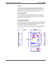
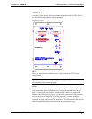
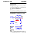
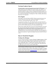
A number of ports bearing silk-screened labels are located on the CNXFZ. Refer to
the illustration and descriptions after this paragraph.
CNXFZ Front Panel
CNXFZ
NET
This 6-pin, 6-position RJ11 modular jack is used to connect the CNXFZ to the
control system.
NOTE: Review the latest revision of the Network Modular Cable Requirements
(Doc. 5682). Most 4-conductor phone cables are wired in a crisscross fashion and are
not compatible with Crestron equipment.
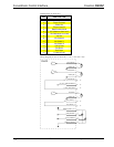
LENS
This DB15 female connector provides three channels for zoom, focus, and iris, as
well as additional signals depending on lens. Refer to the pinout table on the next
page. A 15-pin D-sub male connector with hood (P/N 748048-1) is supplied and
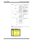
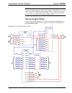
attaches to the LENS port. To properly wire this male connector, a wiring schematic
for each lens type (A through D) follows the pinout table. Crestron maintains a
limited number of cabling drawings for lenses. Refer to “Appendix: Application
Examples” on page 18 for specific lens applications. The information in the appendix
offers recommended cabling connections with the appropriate lens type.
Operations Guide - DOC. 5753 CNX Focus/Zoom Control Interface: CNXFZ • 3