


5
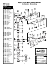
Disassembly/Assembly Instructions - Right Angle Tools
Important: Manufacturer’s warranty is void if tool is disassembled before warranty expires.
Please refer to parts breakdown for part identification.
Motor Disassembly:
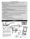
1. Shut the air supply and disconnect the sander from the air supply hose. Important: Hold the air inlet adapter securely with a wrench before removing the air fitting so as
to prevent damage to the composite housing.
2. Secure the motor housing in a vise by using the 52296 Repair Collar to provide protection for the housing. Position the tool so that the angle head is pointing up.
3. Use a 34mm or an adjustable wrench to remove the 01461 Lock Nut by turning it clockwise.
4. Pull the motor assembly out of the motor housing.
5. Fasten the 96346, 2" Bearing Separator around the portion of the 01476 Cylinder that is closest to the 02676 Rear Bearing Plate.
6. Place the bearing separator on the table of the arbor press so that the pinion gear end of the rotor is pointing toward the floor.
7. Use a 3/16" dia. flat end drive punch as a press tool and position it on the rotor shaft. Press the rotor out of the 02696 Bearing. The 02696 Bearing can be removed from the
02676 Bearing Plate with the 96210 Bearing Removal Tool and the 96232 Arbor Press (#2).
8. Secure the body of the rotor in a vise with bronze or aluminum jaws so that the pinion gear is pointing up.
9. Use a wrench to remove the pinion gear from the rotor by turning it counterclockwise.
10. Pull the 01478 Front Bearing Plate with bearing off the rotor.
11. Push the 02649 Bearing out of the front bearing plate and remove the shims.
12. Slip the 01479 Spacer off the rotor.
Motor Disassembly Complete.
Orbital Head Disassembly:
1. Shut the air supply and disconnect the sander from the air supply hose.
2. Remove the pad.
3. Use a Phillips
®
screwdriver to remove the 97175 Screws (4).
4. Use a sharp utility knife to cut through and remove the 30709 Boot Clamp. Important: Cut the clamp carefully so as to prevent personal injury and damage
to the 30700 Boot.
5. Pull the 30700 Boot from the 02052 Housing.
6. Hold the 30703 Counterweight stationary with a 19mm open-end wrench. Use a Phillips
®
screwdriver to loosen the 97174 Screw and remove the 30702 Balancer Shaft.
7. Use a 5/64" (2mm) slotted screw, screwdriver to remove the 97172 Snap Ring.
8. Use the 96210 Bearing Removal Tool and the 96232 Arbor Press (#2) to push the 30705 Bearings (2) out of the balancer shaft.
9. Use a 2mm Hex Key to remove the 97173 Set Screw and the 30703 Counterweight.
Orbital Head Disassembly Complete.
Right Angle Housing Disassembly:
1. Shut the air supply and disconnect the sander from the air supply hose.
2. Secure the 30710 / 30712 Housing in a vise by using the 52296 Repair Collar to provide protection for the housing. Position the housing so that the 02035 Lock
Ring is facing up.
3. Use the 50971 Lock Ring Tool to remove the 02035 Lock Ring, by turning it counterclockwise.
4. Grasp the shaft to pull the shaft, the 54520 Bearing, the gear and the shims out of the housing.
5. The bearing and gear can be pressed off the spindle with the 96232, Arbor Press (#2).
6. If necessary the 02033 Needle Bearing can be removed by using a 5/16" dia. flat end drive punch to push the 02041 Gear Oil Plate, and 01041 Gear Oil Fitting out
of the 02052 Housing.
Right Angle Housing Disassembly Complete.
Valve Disassembly:
1. Use the 52296 Repair Collar to securely hold the motor housing in a vise so that the inlet adapter is pointing up.
2. Remove the valve components by loosening the inlet adapter. Remove the 01468 Spring, 01472 Tip Valve, and 01464 Seal.
3. Reposition the motor housing in the vise so that the throttle lever, and the 12132 Pin are accessible. Remove the pin and lever by using a 2.5mm dia. drive punch.
4. Use retaining ring pliers to remove the 95558 Retaining Ring and push the 01469 Speed Regulator Assembly out of the motor housing.
Valve Disassembly Complete.
Important: Clean and inspect parts for wear or damage before assembling.
Valve Assembly:
1. Install the 01469 Speed Regulator Assembly into the motor housing, and secure it in place with the 95558 Retaining Ring.
2. Use the 52296 Repair Collar to securely hold the motor housing in a vise so that the air inlet is pointing up.
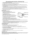
3. Insert the 01449 Valve Stem into the speed regulator assembly so that the hole in the valve stem aligns with the air inlet hole in the motor housing.
4. Install the 01464 Seal so that it lays flat. Use a needle nose pliers to grasp the nylon portion of the 01472 Tip Valve and install it so that the metal pin fits into the hole
of the 01449 Valve Stem.
5. Install the 01468 Spring so that the smaller end fits against the back of the tip valve.
6. Refer to the parts breakdown for part identification and the sequence of assembly. Apply a small amount of Loctite
®
#567 (or equivalent) to the male threads of the
inlet adapter and tighten the inlet adapter. (Torque to 23 N-m/200 in. lbs.)
Valve Body Assembly Complete.
Motor Assembly:
1. Secure the body of the rotor in a vise with bronze or aluminum jaws so that the threaded end is pointing up.
2. Slip the 01479 Spacer onto the 02037 Rotor.
3. Select .003 (.08mm) thick shims from the 54529 Shim Pack and place these into the 01478 Front Bearing Plate.
4. Install the 02649 Bearing into the front bearing plate and slip the bearing/plate assembly onto the rotor.
5. Install the pinion onto the rotor, making it hand tight.
(continued on next page)