


Disassembly/Assembly Instructions - Right Angle Tools
6. Check the clearance between the rotor and the bearing plate with a .001 thick feeler gauge. Clearance should be .001” to .0015” (0.03-0.04mm). If it’s necessary, readjust
clearance by repeating steps 3-5 with different thickness shims.
7. Once the proper rotor/plate clearance is achieved wrench tighten the pinion. (Torque to 17N·m/150 in. lbs.)
8. Apply the 95842 Dynabrade Air Lube (10W/NR or equivalent) to the 01480 Blades and install them onto the rotor.
9. Use the 96216 Bearing Press Tool so that it pushes against the outer race of the 02696 Bearing and install it into the 02676 Rear Bearing Plate with the arbor press.
10. Place the pinion on the tool plate of the arbor press so that the rear portion of the rotor is pointing up.
11. Install the 01476 Cylinder so that it rests against the 01478 Bearing Plate. Note: Make sure that the air inlet passage of the cylinder will properly aligned with the air inlet
passage in the 02676 Bearing Plate.
12. Use the 96216 Bearing Press Tool so that it pushes against the inner race of the 02696 Bearing and install the rear bearing/plate assembly onto the rotor with the
arbor press. Important: Carefully press the rear bearing/plate assembly onto the rotor until it touches the 01476 Cylinder. A “snug” fit should exist between the bearing
plates and cylinder. If it is too tight the rotor will not turn freely and will cause damage to the bearings. If it is too loose the proper bearing preload will not be achieved.
13. Apply a small amount of grease to the seal of the 02696 Rear Bearing and place the 02679 Shield against the seal of the bearing.
14. Install the motor assembly into the housing so that the air passage node of the rear bearing plate aligns with the air passage notch inside the housing.
15. Apply a small amount of Loctite
®
#567 (or equivalent) to the threads of the motor housing and use a 34mm (or an adjustable wrench) to connect the angle head assembly
to the motor housing. (Torque to 34 N-m/300 in. lbs.)
Motor Assembly Complete.
Right Angle Housing Assembly:
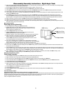
1. Press the 01041 Gear Oil Fitting into the 02041 Gear Oil Plate.
2. Carefully apply two drops of Loctite
®
#680 (or equivalent) to the recessed area of the
02052 Housing and press the gear oil plate along with gear oil fitting into the housing.
(Allow 30 minutes for the adhesive to cure.)
3. Press the 02033 Needle Bearing into the housing.
4. Position the 96239 Bearing Press Tool so that it rests against the inner race of the
54520 Bearing and press the bearing onto the spindle.
5. Align the hex shaped I.D. area of the gear with that of the spindle and press the gear into place.
6. Apply a small amount of Loctite
®
#567 (or equivalent) to the mating threads of the 02052
Housing. Connect these parts while being aware of the right and left hand threads.
7. Place the 52296 Repair Collar around the motor housing and position the tool in a vise so
that the angle housing end of the tool is pointing up.
8. Use a 34mm or adjustable wrench on the 01461 Lock Nut while holding the angle housing
stationary with one hand. Note: The throttle lever can be positioned in 360˚ to the desired location.
Allow for additional rotation when tightening the lock nut. (Torque to 34 N-m/300 in. lbs.)
9. Reposition the tool assembly in the vise so that the opening in the angle housing, for the 02035 Lock Ring is facing up.
10. Soak the wicks in the 95848 Gear Oil before installing them into the 02052 Housing. Install the top wick first followed by the bottom wick. Position truncated side of each
wick toward the end of the pinion gear.
11. Install the 30704 Shaft into the angle housing. Apply a slight amount of pressure down on the spindle while rotating it back and forth checking for the proper backlash or fit
between the gears. A slight amount of backlash or clearance should exist between the bevel and pinion gears. When a tight fit exist, then add shims as needed placing the
required thickness of shims between the outer race of the 54520 Bearing and the bearing seat in the housing.
12. Place (1) 01486 Felt Silencer into the 02035 Lock Ring, and apply a small amount of Loctite
®
#567 (or equivalent) to the threads of the 02035 Lock Ring. Use the
50971 Lock Ring Wrench to install the lock ring onto the 02052 Housing. (Torque to 23 N-m/200 in. lbs.)
Right Angle Housing Assembly Complete.
Orbital Head Assembly:
1. Install the 30703 Counterweight onto the 30704 Shaft, aligning the screw hole with the pilot hole in the shaft.
2. Apply a small amount of the Loctite
®
#567 (or equivalent) to the threads of the 97173 Set Screw.
3. Use a 2mm hex key to install the 97173 Set Screw into the 30703 Counterweight and secure the counterweight to the 30704 Shaft.
4. Use the raised outer diameter of the 96216 Bearing Press Tool and the 96232 Arbor Press (#2) to press the 30705 Bearings (2) into the 30702 Balancer Shaft.
5. Install the 97172 Snap Ring into the 30702 Balancer Shaft.
6. Install the balancer shaft assembly onto the 30704 Shaft.
7. Apply a small amount of the Loctite
®
#567 (or equivalent) onto the threads of the 97174 Screw. Hold the 30703 Counterweight stationary with a 19mm open-end wrench.
Use a Phillips
®
screwdriver to tighten the 97174 Screw into the 30704 Shaft.
8. Install the 30700 Boot and the 30701 Plate, aligning the screw holes.
9. Install the 97175 Screws (4) securely.
10. Install the 30709 Boot Clamp around the 30700 Boot and use a HEAT GUN to shrink-fit the clamp, securing the boot to the 02052 Housing.
11. Install the pad.
Orbital Head Assembly Complete.
Tool Assembly Complete. Please allow 30 minutes for adhesives to cure before operating tool.
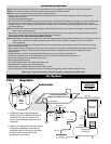
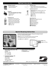
Important: Before operating, place 2-3 drops of Dynabrade Air Lube (P/N 95842) directly into air inlet with throttle lever depressed. Operate tool for 30 seconds to determine if tool
is operating properly and to allow lubricating oils to properly penetrate motor. Motor should now be tested for proper operation at 90 PSIG. If motor does not operate properly or
operates at a higher RPM than marked on the tool, the tool should be serviced to correct the cause before use.
Loctite
®
is a registered trademark of Loctite Corp.
6
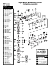
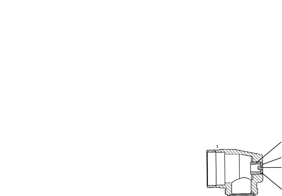
02052 Housing 02033 Needle Bearing
02041 Gear Oil Plate
2 Drops of Loctite
01040 Gear Oil Fitting