


2
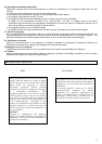
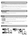
Section name and functions
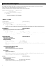
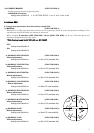
Connector
Signal connection to IEEE1394.b (PORT1/PORT2) Viewer Soft Setting (PORT1/PORT2)
1 TPB- *Programmable I/O In Out
2 TPB+ Trigger
○○
3 TPA- VD
○○
4 TPA+
SPECIAL DATA
Strobe (Flash pulse)
×○
5 TPA (R) SHIELD GND
6 VG POWER GND
7 I/O * Programmable I/O
8 VP POWER +12V
9 TPB (R) SHIELD GND
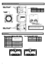
Camera / Tripod adaptor
mounting screw holes
Camera / Tripod adaptor
mounting screw holes
Lens mount
(C mount)
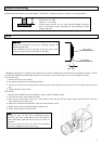
*1
When power is supplied from IEEE1394,
check for proper current and voltage.
IEEE1394 connectors
*1
Connect to IEEE1394 connector
of PC using IEEE1394 cable.
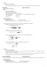
POWER/STATUS LED
LED Green Yellow
Power ON Light Off Light off
Transmission Blink Off Blink On
Transmission pause Blink On Blink Off
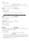
PLATE,RATED
POWER/STATUS
PORT 2PORT 1
12 34
5 6 7 8 9
1 234
5 6 7 8 9
PORT2 PORT1