


14
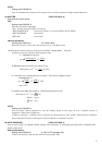
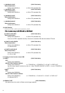
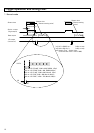
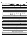
4. Reset control (External trigger operating mode: Mode 14)
When the external trigger signal is HIGH ACTIVE, exposure begins at the rising edge of the trigger signal and ends at the
falling edge. At the Readout pulse falling edge, the internal VD signal is reset and the video data are transmitted.
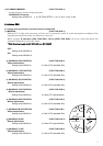
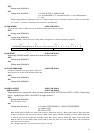
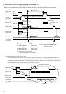
Note: Special function of rest control trigger
The camera shifts to the output of a normal mode (continuous output) when Trigger B signal passes about 1/3
seconds in the state of High. (The image is output by inputting the Trigger at the VD cycle for this period.)
It returns to the Reset control mode if Trigger B signal becomes Low. However, after becoming Low Trigger B, the
period of 50 ms becomes a Trigger A signal input prohibition period.
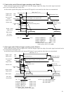
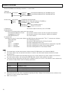
Trigger input
(High active)
Shutter time
Readout pulse
(High active)
Strobe output
(High active)
High
Low
Shutter time
(integration time)
Data output
Shutter time
(integration time)
9H
More than 10μs
T2 (*7)
More than T1
(*1)
1~250ms
VD output
(Low active)
Trigger
delay
(*3)
Strobe delay
(*4)
Strobe duration1
(*5)
Strobe duration2 (*6)
More than 10μs
Output delay
(*2)
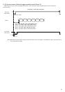
Port1/Port2
output
(High active)
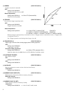
Port1/Port2 (Trigger) input signal width
[sec]
rate frameSelf
1
T1 (*1) =
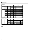
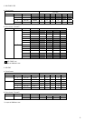
(*2) 0.19~3930.43μs 0.96μs/step
(*3) 0.22~3930.46μs 0.96μs/step
(*4) 0.28~3930.52μs 0.96μs/step
(*5) 0.96~3931.2μs 0.96μs/step
(*6) Shutter Time – Strobe delay
(when duration time is set to 000h)
(*7) T2 = 93μs (KP-FD140F/F140F)
(*7) 56μs (KP-FD32F/F32F)
(*7) 58μs (KP-F83F)
More than 10μs
Trigger input
(High active)
High
Low
Shutter time
Shutter time
(integration time)
Data output
Readout pulse
(High active)
1~250ms
1/3s approx.
VD output
(Low active)