


CV-M91
- 18 -
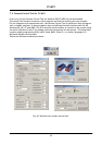
7. Configuring the Camera
7.1 Switch settings
The switch positions are shown in factory setting. Names in bold italic is factory setting.
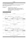
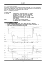
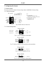
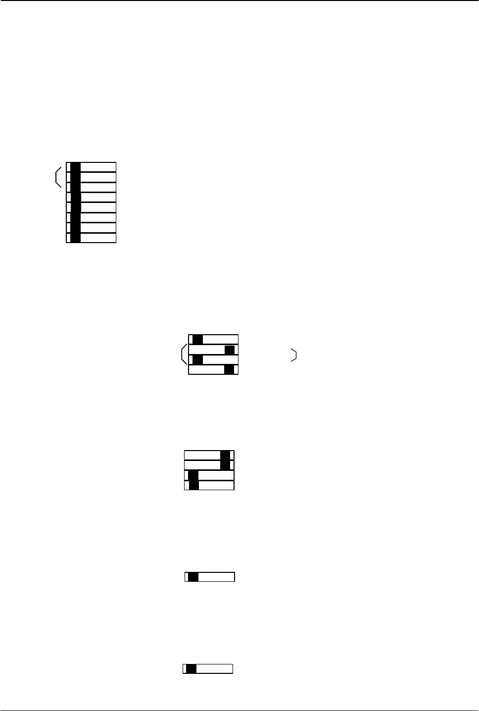
7.1.1. SW1 on rear panel
<
<
<
<
<
>
<
>
<
<
>
>
>
<
<
>
<
>
>
>
<
>
>
>
1/60
1/125
1/250
1/500
1/1000
1/2000
1/4000
1/10,000
second
OFF
ON
1
2
3
4
5
6
7
8
CONTROL
GAMMA
TRIGGER
SHUTTER
GAIN
INTERLACE
Gam. 1
< >
Gam. 0.45
Normal
< >
Random
Man.
< >
< >
Intel.
< > Non-interl.
.
AGC
Local
RS-232C
SW 1 on rear
Note:
SW1-1 through 3 OFF:
In Normal mode: The shutter is OFF
In Trigger mode: 1/50 for PAL. 1/60 for NTSC
SW1-1 through 2 OFF. SW1-3 ON:
In Normal mode: 1/100
In Trigger mode: 1/125
Fig. 30. Mode switch on camera rear
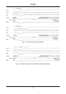
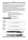
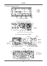
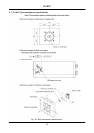
7.1.2. Switch settings inside
ON
OFF
1
2
3
4
VBS out
Y/VBS out
VBS
< >
NC
Sync on G
G+S < > G
> <
< >
Y - VBS
SW 604 on PK 8404
On pin #4 12P
On pin #6 9P
On pin #4. 9P
Fig. 31. Switch on PK8404 for video output.
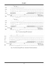
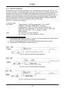
OFF
ON
1
2
3
4
HD term.
TTL
< >
75 Ohm
SW 301 on PK 8407
VD term.
Trig term.
Accumul.
TTL
< >
75 Ohm
TTL
< >
75 Ohm
field
< >
frame
Fig. 32. Switch on PK8407 for 75Ω termination and accumulation.
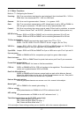
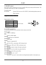
OFF
ON
1
CCD iris
Off
< >
CCD iris on
SW 201 on PK 8408
Fig. 33. Switch on PK8408 for CCD iris.
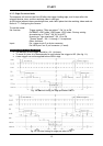
OFF
ON
1
White bal.
Man.
< >
One push
SW 202 on PK 8408
Fig. 34. Switch on PK8404 for white balance.