


CV-M91
- 4 -
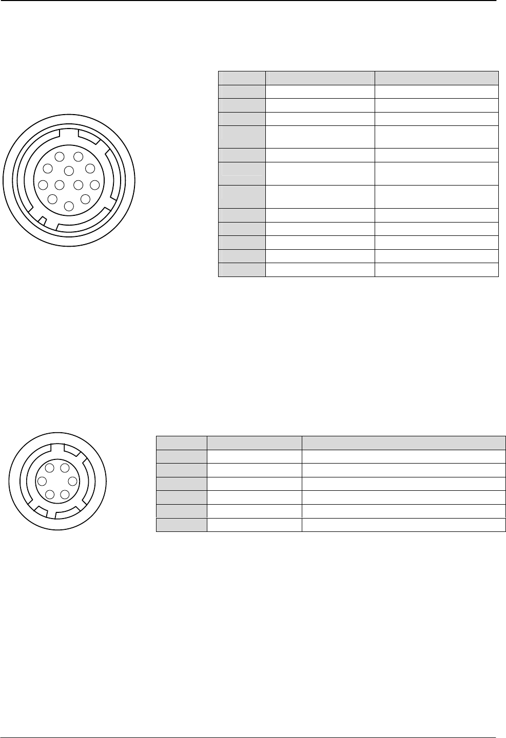
5. Pin Assignment
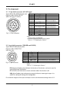
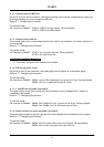
5.1. 12-pin Multi-connector (DC-IN/Trigger)
Type: HR10A-10R-12PB-01(Hirose) male.
Plugs for cable: HR10A-10P-12S
(Seen from rear of camera.)
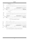
Fig. 2. 12-pin connector.
Notes:
Pin no. Signal Remarks
1 GND
2 +12 V DC input
3 N/C
4 NC/VBS video out
*), VBS 75 Ω source
SW604-1 on for VBS out
5 GND
6 HD in/HD out
75 Ω term. By SW301-1
*), HD out 75 Ω source
7 VS in/VD in/VD out
75 Ω term. By SW301-2
*), VD out 75 Ω source
8 GND
9 NC/Pixel clock out
*), 75 Ω source
10 GND
11 +12 V DC input
12 GND
3
4
5
6
7
8
9
10
11
12
1
2
Factory setting in bold italic.
*) Alternative signal by internal switch/jumper
Refer to “7. Configuring the Camera.”
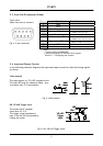
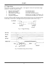
5.2. 6-pin Multi-connector (TRIGGER and RS232C)
Type: HR10A-7R-6PB (Hirose) male
Plugs for cable: HR10A-7P-6S
Seen from rear.
1
2
3
4
5
6
Pin no. Signal Remarks
1 TXD out
RS-232C
2 RXD in
RS-232C
3 GND
4 EEN output
75 Ω source
5 Trigger input
75 Ω termination by int. switch SW301-3
6 WEN output
75 Ω source
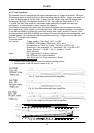
Fig. 3. 6-pin connector.
Notes:
Refer to “7. Configuring the Camera.”
EEN (Exposure Enable) pulse indicates the duration of the shutter, and can be used for
controlling strobe illumination.
EEN will be low all the time in normal continous mode if the shutter is off.
WEN (Write Enable) pulse indicates the period of effective video signal output. It is
usefull for setting the timing with framegrabber.
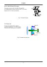
For schematic diagram of the input and output circuit with alternative settings refer to 5.3.