


CV-M91
- 5 -
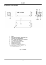
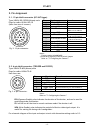
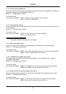
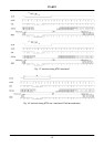
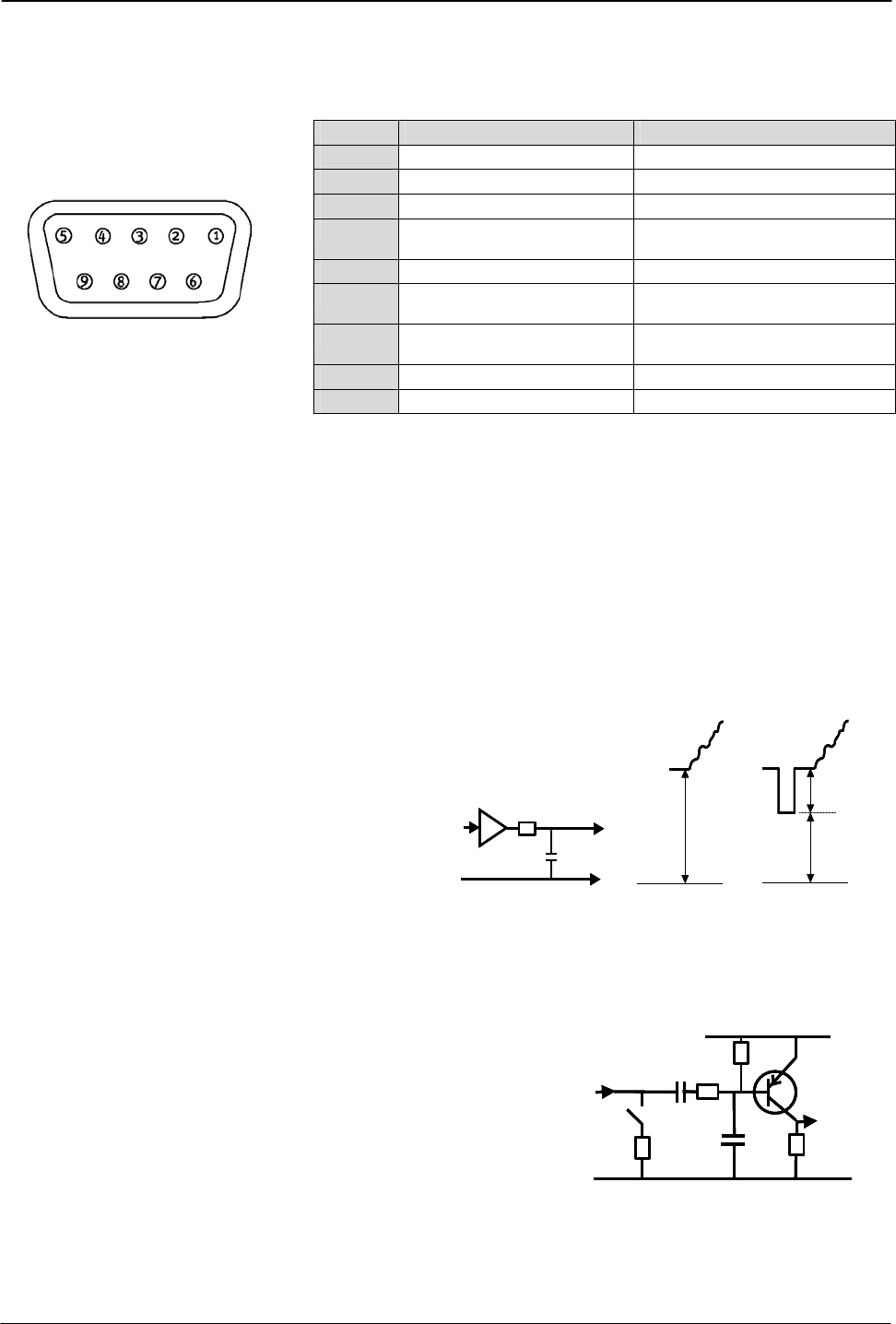
5.3. 9-pin Sub D-connector (Video)
Type: male.
N
Pin no. Signal Remarks
1 GND
2 GND
3 R output
75 Ω source.
4 G out or G+S output
75 Ω source.
*) , SW604-4 off for G out
5 B output
75 Ω source
6 Y video out or VBS out
75 Ω source.
*), SW604-2 off –3 on for Y out
7 Sync out or WEN out
75 Ω source
*), JP303 o JP304 c for Sync out
8 GND
9 C video out
75 Ω source
(Seen from rear of camera.)
Fig. 4. 9-pin connector.
Notes:
Factory setting in bold italic.
*) Alternative signals by internal switch/jumper.
Refer to “7. Configuring the Camera.”
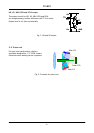
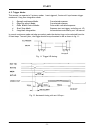
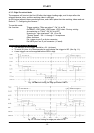
5.4. Input and Output Circuits
In the following schematic diagrams the input and output circuits for video and timing signals
are shown.
Video outputs
300 mV
500 mV
GND
75
Video
Output
800 mV
300 mV
500 mV
300 mV
500 mV
GND
75
Video
Output
GND
75
Video
Output
800 mV
800 mV
The video output is a 75 Ω DC coupled circuit.
The video DC level for video and video + sync
are shown with 75 Ω termination.
Fig. 5. Video output.
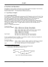
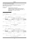
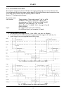
HD, VD and Trigger input
VD, HD,
Trigger
input
+5V
47p
33k
1k2
75
10u
VD, HD,
Trigger
input
+5V
47p
33k
1k2
75
10u
+5V
47p
33k
1k2
75
10u
The inputs are AC coupled.
Input level 4 V ±2 V.
The trigger input impedance is
high. It can be 75Ω terminated by
closing the switch.
Fig. 6. HD, VD and Trigger input.