


Page 14
TM-6760 Series Progressive Scan Shutter Cameras
Operation
3 Operation
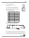
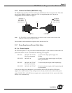
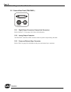
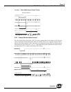
3.1 Camera Rear Panel (TM-6760, LVDS model only)
3.1.1 Up/Down Switch
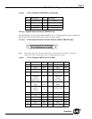
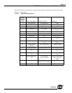
The Mode Selection switch works in conjunction with the Up/Down switch. Refer to Table 6 on
page 15 for information on the Up/Down switch.
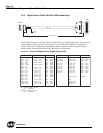
3.1.2 Digital Output Connector
Refer to Section 2.2.2 (c on page 7 for information on the digital output connector.
3.1.3 Analog Output Connector
The TM-6760 camera has a BNC connector on the rear panel to output analog video data.
3.1.4 Power, RS-232, and External Sync Connector
Refer to Section 2.2.2 on page 6 for information on the power, RS-232, and external sync connector.
3.1.5 Shutter Speed Control Switch
Please refer to Section 2.2.3 on page 9 for information on the Shutter Speed Control switch. The factory
default setting to the shutter speeds is no shutter.
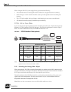
3.1.6 Mode Selection Switch
Various modes can be implemented with the rear panel Mode Selection switch. The Mode Selection
switch works in conjunction with the Up/Down switch and RS-232 external control. Commands from
SHUTTER MODE
UP
DOWN
POWER
VIDEO
0
9
8
7
6
5
4
3
1
2
1
0
F
E
D
C
B
A
2
3
4
5
6
7
8
9
DIGITAL
1
2
3
4
5
6
9
8
7
11
12
10
Up/Down switch
Digital Output connector
Analog Output connector
Power, RS-232, and
External Sync Connector
Mode Selection switch
Shutter Speed
Control switch