


17
7. Place Natural gas orifice in plastic parts bag for future use
and keep with package containing literature.
8. Replace the burner base using both screws.
9. Replace burner head and cap.
10. Repeat steps 2 through 9 for the remaining burners.
Complete Installation
1. Refer to the “Make Gas Connection” section for properly
connecting the range to the gas supply.
2. Refer to the “Electronic Ignition System” section for proper
burner ignition, operation, and burner flame adjustments.
IMPORTANT: You may have to adjust the “LO” setting for
each cooktop burner.
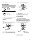
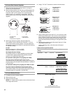
Checking for proper cooktop burner flame is very important.
The small inner cone should have a very distinct blue flame
¼" (0.64 cm) to ½" (1.3 cm) long. The outer cone is not as
distinct as the inner cone. LP gas flames have a slightly
yellow tip.
3. Refer to “Complete Installation” in the “Installation
Instructions” section of this manual to complete this
procedure.
Natural Gas Conversion
1. Turn manual shutoff valve to the closed position.
2. Unplug range or disconnect power.
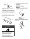
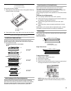
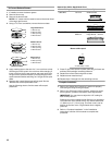
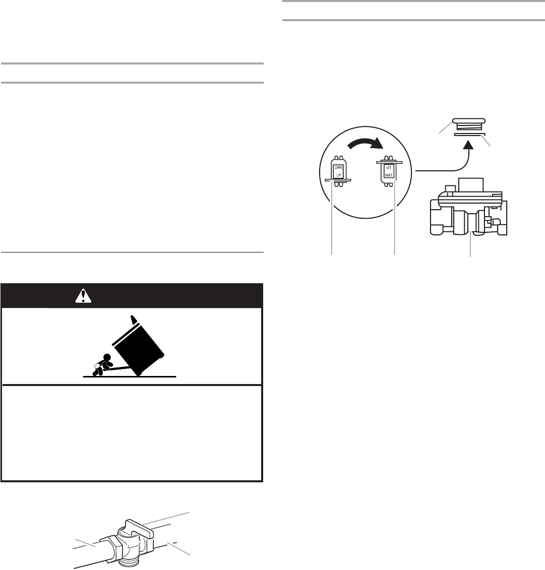
To Convert Gas Pressure Regulator
1. Remove the access cap by using a wrench, turning the
access cap counterclockwise.
2. Remove spring retainer from the cap by pushing against the
flat side of the spring retainer. Look at the spring retainer to
locate the “LP” or “NAT” position. Turn over the spring
retainer so the “NAT” is showing on the bottom. Snap the
spring retainer back into the cap. Reinstall the cap onto the
regulator.
3. Test the gas pressure regulator and gas supply line.
The regulator must be checked at a minimum 1" (2.5 cm)
water column above the set pressure. The inlet pressure to
the regulator should be as follows for operation and checking
the regulator setting:
Natural Gas:
Minimum pressure 6" (15.2 cm) WCP
Maximum pressure 14" (35.6 cm) WCP
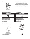
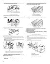
Gas Supply Pressure Testing
Gas supply pressure for testing regulator must be at least
1" water column pressure above the manifold pressure
shown on the model/serial rating plate.
Line pressure testing above ½ psi gauge (14" WCP)
The range and its individual shutoff valve must be
disconnected from the gas supply piping system during any
pressure testing of that system at test pressures in excess of
½ psi (3.5 kPa).
Line pressure testing at ½ psi gauge (14" WCP) or lower
The range must be isolated from the gas supply piping
system by closing its individual manual shutoff valve during
any pressure testing of the gas supply piping system at test
pressures equal to or less than ½ psi (3.5 kPa).
A.To range
B. Shutoff valve (closed position)
C.Gas supply line
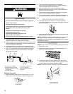
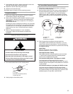
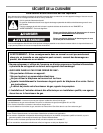
WARNING
Tip Over Hazard
A child or adult can tip the range and be killed.
Connect anti-tip bracket to rear range foot.
Reconnect the anti-tip bracket, if the range is moved.
Failure to follow these instructions can result in death
or serious burns to children and adults.
A
B
C
A.Access cap
B.Gasket
C.Gas pressure regulator
D. NAT position
E.LP position
A
B
CDE