


21
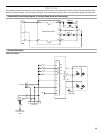
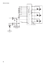
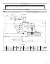
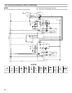
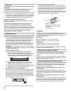
Wiring Diagrams
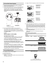
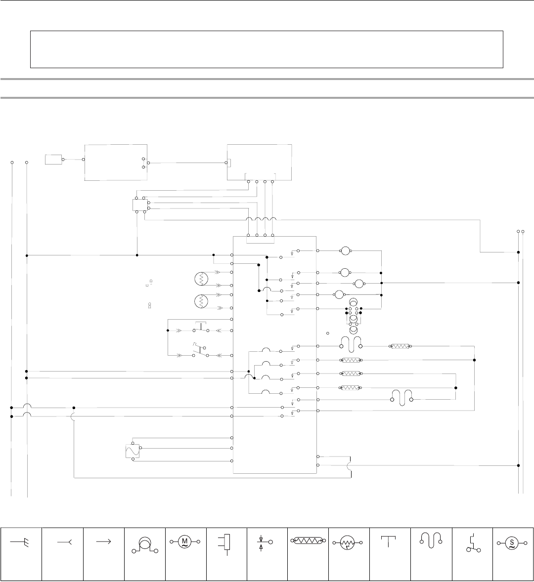
30"/36" (76.2 cm/91.4 cm) Oven Schematic for JDRP and YJDRP Models
NOTES:
■ End of line tester is for manufacturing purpose only.
■ Dots indicate connections or splices.
■ Circuit shown in STANDBY/OFF mode with oven door closed.
Caution: Label all wires prior to disconnection when servicing controls. Wiring errors can cause improper and dangerous operation.
Verify proper operation after servicing.
Inner BroilL-3490W (30"/36")
Conv-2800W
Outer Broil-1986W (30")
Bake-3000W
T1-1
P6-4
P6-2
BU
R
OR
P8-6
T3-1
T3-3
T3-2
T3-4
P8-5
T4-3
T4-4
P8-4
P3-3
P9-2
P3-4
LS Cooling Fan
Y
P3-5
P9-5
P6
APPLIANCE
MANAGER
T2-2
T1-2
P8-1
P8-3
Hall Sense
T2-1
Halogen Oven Light
P6-1
P6-5
R
L1
L2
HMI KEYBOARD
15 PIN
ATLAS BOARD
N
LCD
BK
Y
BK
OR
GY
BU
BK
BK
BK
Y
BK
R/W
Latch Motor
15 PIN
Y
L2
P7-3
P7-1
Meat Probe
Temp Sensor
1654
AT 177 ˚C (350 ˚ F)
V
V
P2-1
P2-5
W
W
W
W
78k
AT 15.6 ˚ C (60 ˚ F)
37k
AT 32.2 ˚ C (90 ˚ F)
P2-6
P2-2
OR
W
t˚
t˚
P1-7
Latch Switch
(Operated by Motor)
Door Switch
P1-5
P1-4
BR
OR
T
BU
BU
BR
BR
T
OR
Strobe
W
W
R
BK
BK
W
R
1080
AT 21 ˚C (70 ˚ F)
ConvectT Fans
HS Cooling Fan
M
~
BK
W
J1-3
J1-4
J2-2
J2-5
J2-4
J2-1
R
R/W
R
R
Y
Temperature Cutoff
(Non-Resettable)
Temperature Cutoff
(Non-Resettable)
BU
BU
BU
R
Y
Y
R
M
~
BU
OR
M
~
M
~
3000W (36")
(J900-1 to J900-15)
J4-12
J4-11
J4-8
J4-7
OR
BR
Switch Mode
Power Supply
(SMPS)14 VDC 45W
LEGEND
Ground
(Chassis)
Plug With
Female
Connector
Receptacle
With Male
Connector
Light
Thermal Cutoff
(Non-
Resettable)
Operated
By Door
Relay Coil
AC Drive
Motor
Enclosed
Thermistor
Relay Contact
Heating
Element
Thermostat
Fill Valve