


EN87
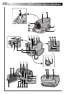
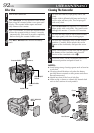
Controls
1 Flash Switch [FLASH OPEN] ................ ੬ pg. 34
2 Shooting Mode Dial
[PS, VIDEO, DUAL,␣ VGA, XGA] .......... ੬ pg. 15
3 Dioptre Adjustment Control ................... ੬ pg. 8
4 Battery Release Button [BATT. RELEASE] .... ੬ pg. 7
5 •MENU Wheel [+, –, PUSH] ............... ੬ pg. 30
•LCD Monitor BRIGHT
(Brightness) Control [+, –] .................. ੬ pg. 16
6 •Power Zoom Lever [T/W] .................. ੬ pg. 22
•Speaker/Headphone Volume Control
[VOL.] .............................................. ੬ pg. 44
7 Snapshot Button
[SNAPSHOT]................੬ pg. 18, 20, 24, 26, 67
8 OPEN/EJECT Switch ............................. ੬ pg. 10
9 SLOW Button ................................ ੬ pg. 29, 45
0 Snapshot Mode Button [SNAP MODE] ... ੬ pg. 18
! INDEX SCREEN Button .................. ੬ pg. 19, 49
@ PRINT FRAME Button .......................... ੬ pg. 52
# PRINT Button
Enables printing using the optional printer
equipped with a PRINT DATA connector. Refer to
the separate “FOR OWNERS OF AN OPTIONAL
PRINTER” instruction sheet.
$ Monitor Open Button
[PUSH-OPEN] ............................... ੬ pg. 12, 16
% •Play/Pause Button [
4
/6] ................... ੬ pg. 44
•High Speed Recording Button
[HIGH SPEED] .................................. ੬ pg. 28
^ •Stop Button [5] ................................. ੬ pg. 44
•FOCUS Button .................................. ੬ pg. 27
& •Fast-Forward Button [
3
] ................. ੬ pg. 44
•SPOTLIGHT Button ........................... ੬ pg. 42
* •Rewind Button [
2
] ......................... ੬ pg. 44
•BACKLIGHT Button .......................... ੬ pg. 42
( Power Switch
[ , , , , OFF] ........... ੬ pg. 14
) Recording Start/Stop Button.................. ੬ pg. 16
q Lock Button ......................................... ੬ pg. 14
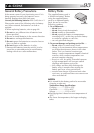
Connectors
The connectors
w
to
r
are located beneath a cover.
w Headphone Connector [PHONE] ......... ੬ pg. 78
No sound is output from the speaker when
headphones are connected to this connector.
e External Stereo Microphone Input Connector
[MIC] .................................................. ੬ pg. 78
r Audio/Video Input/Output Connector: GR-DVL9800
Audio/Video Output Connector: GR-DVL9700
[AV] .............................੬ pg. 58, 59, 62, 63, 73
To connect cables to the following connectors
t
to
o
,
open the LCD monitor.
t Digital Video Connector
[DV IN/OUT: GR-DVL9800,
DV OUT: GR-DVL9700]
(i.link*) .............................. ੬ pg. 60, 61, 64, 65
* i.Link refers to the IEEE1394-1995 industry
specification and extensions thereof. The logo
is used for products compliant with the i.Link
standard.
y J Terminal/Edit Connector [JLIP (Joint Level
Interface Protocol) (EDIT)] .................... ੬ pg. 73
•Connect the editing cable when performing
Random Assemble Editing.
•Connect to a JLIP-compatible camcorder or VCR
to control it from the computer using the
provided Software.
u PC (DIGITAL STILL) Connector ............. ੬ pg. 60
i PRINTER Connector
Connect to the optional printer equipped with a
PRINT DATA connector. Refer to the separate
“FOR OWNERS OF AN OPTIONAL PRINTER”
instruction sheet.
o S-Video Input/Output Connector: GR-DVL9800
S-Video Output Connector: GR-DVL9700
[S-VIDEO] ....................੬ pg. 58, 59, 62, 63, 73
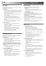
Indicators
p Tally Lamp ........................................... ੬ pg. 16
Q Shooting Mode Indicator...................... ੬ pg. 31
W Power Lamp ........................................ ੬ pg. 16
Other Parts
E Viewfinder............................................. ੬ pg. 8
R Lens Cover
Opens when the viewfinder is pulled out or the
LCD monitor is opened fully.
T •Remote Sensor .................................. ੬ pg. 68
•Camera Sensor
Be careful not to cover this area, a sensor
necessary for shooting is built-in here.
Y Stereo Microphone .............................. ੬ pg. 78
U Flash ................................................... ੬ pg. 34
I Shoulder Strap Eyelets ............................ ੬ pg. 8
O Battery Pack Mount ............................... ੬ pg. 7
P Grip Strap .............................................. ੬ pg. 8
a LCD Monitor ................................. ੬ pg. 16, 17
s Speaker ............................................... ੬ pg. 44
d Stud Hole .............................................. ੬ pg. 8
f Tripod Mounting Socket ......................... ੬ pg. 8
g MEMORY CARD Cover ....................... ੬ pg. 12