


E-10
INTRODUCTION
13
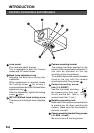
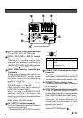
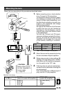
[ , , , ] Up-and-down, left-and-
right Button
These buttons select items on the menu
screen and change a set value.
(੬ Page 23)
14
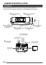
[EXT.TERM-ON/OFF] Terminal On/Off
Switch of External Synchronization
Signal
This is a terminating ON/OFF switch for
the external synchronization input signal.
When this is switched ON, termination is
executed via a 75 Ω resistor.
ON: terminates at 75Ω.
OFF: does not terminate at 75Ω.
(ON: At time of factory shipment)
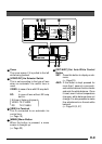
15
[INT/GL, LL] Selector Switch for
Synchronizing System
This switch can set a synchronizing system
of the camera.
INT/GL:
This is set for internal synchronization
(INT) or external synchronization (GL).
LL (Line Lock):
The camera’s vertical synchronization is
locked to the AC 24V power line frequency.
When switching between multiple cameras
using a switcher, selecting this mode and
adjusting the vertical phase can reduce the
monitor sync disturbances occurring when
the camera image is switched. (This cannot
be used in regions where the power
frequency is 60 Hz (50 Hz) ( ): TK-C1460U)
(INT/GL: At time of factory shipment)
16
[DUPLEX, SIMPLEX] Selector Switch
for Transmission System
If the setting is changed, be absolutely
sure to switch on the power again.
DUPLEX:
This switch sets to DUPLEX when the
transmission between the camera and a
remote control unit is in a duplex system
(two-way).
SIMPLEX:
This switch sets to SIMPLEX when the
transmission between the camera and a
remote control unit is in a simplex system
(one-way).
(DUPLEX: At time of factory shipment)
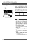
17
[RX.TERM-ON/OFF] RX Signal Terminal
ON/OFF Switch
This sets whether or not the signal
between RX + and RX – on the back
20
should be terminated at the value of
110Ω resistance.
ON: terminates.
OFF: does not terminate.
If the system including the camera is the
M.DROP (Multi-drop, RS-485) system,
only the camera mounted at the terminal
of control signal cable is set to “ON” and
the other camera is set to “OFF”. In case
of the M.DROP system, it becomes
necessary to set the Machine ID. (੬ Page
35)
If the system including the camera is the
P TO P (Point to Point, RS-422A) system,
set this switch of all the cameras to “ON”.
The item STYLE on the COMMUNICA-
TION screen sets M.DROP or P TO P
(੬ Page 35)
(ON: At time of factory shipment)
18
NOT USED
This cannot be used. Do not switch.
Controls, Connectors and Indicators (Continued)