


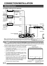
E-11
DC12V
AC24V
Y/C OUT
SYNC IN
POWER
VIDEO OUT
SEE INST-
RUCTION
MANUAL
+
-
12
CLASS 2 ONLY(U TYPE)
ISOLATED POWER ONLY
(E TYPE)
TX
+
TX
-
RX
+
RX
-
AUX
GND
A
B
CD
⁄
)
(
fi
›
¤
‹
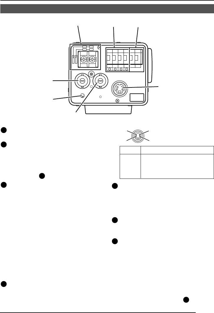
19
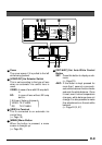
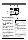
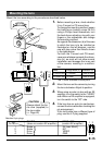
[DC 12V, AC 24V] Power input terminals
To input DC 12V or AC 24V power.
20
[TX+A, TX-B, RX+C, RX-D] Control
signal connection terminals
Terminals for inputting signals with
electrical characteristics conforming to
the EIA/TIA RS-422A or RS-485 standard.
(੬ Page 10
17
RX.TERM switch)
21
[AUX, GND] Auxiliary Input/Output
Terminals
If there is any change in the area set on
the MOTION DETECT screen, these
terminals output the corresponding
signals. (੬ Page 34)
These terminals also output the B&W/
COLOUR signal. (੬ Page 30)
[Open-collector low signal. Maximum
voltage 30V, current 30mA.]
When carrying out B&W/COLOUR
switching using the control signal, the
signals are input through these terminals.
(੬ Page 30)
[B&W: make; COLOUR: break]
22
[Y/C OUT] Y/C output connector
This 4-pin connector outputs the luminance
and chrominance signal.
• Pin configuration of Y/C OUT connector
23
[VIDEO OUT] Video signal output
connector
This BNC connector outputs a composite
video signal. Connect this to the video input
connector of a video monitor, switcher, etc.
24
[POWER] Power indicator lamp
This lamp lights when power is supplied
to the camera.
25
[SYNC IN] Sync signal input connector
This BNC connector accepts the input of
an external sync signal such as a composite
video (VBS) or black burst (BB) signal.
When a sync signal is input into this
connector, the camera operation is
automatically synchronized with the
external sync signal.
To terminate this connector at 75Ω, turn
ON the EXT.TERM switch
14
.
Pin No. Signal
1 GND
2 GND
3 Luminance (Y)
4 Chrominance (C)
4
2
3
1