E-34
MENU SETTING
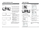
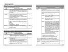
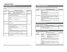
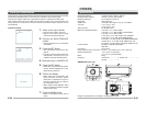
MOTION DETECT Screen
Item Functions and set values Initial value
MODE
Settings are executed about the motion detecting function that emits alarm signals when
there exists any motion in the image. Alarm signals are output from the auxiliary terminals on
the back.
This sets ON/OFF of motion detecting function.
OFF: Motion detecting function does not work.
ON: Motion detecting function works.
OFF
LEVEL
AREA EDIT
ALARM TIME
DEMONSTRATION
This sets the level that detects motion.
If the item MODE is set to OFF, “---” will appear, and
settings cannot be changed.
To function with large signal level change…decrease the
value
To function with small signal level change…increase the
value
[Set values: –5 to NORMAL to 5]
This sets the range in which the motion detecting function
works.
(੬ Page 39)
This sets the output time of the alarm signal output of
AUX terminal as well as “ALARM” display on the screen
when motion is detected.
If the item MODE is set to OFF, “---” will appear, and
settings cannot be changed.
[Set values: OFF, 5s, 6s, 7s, 8s, 9s, 10s, 15s, 20s, 30s,
1min]
MEMO
Even when the ALARM TIME item is set to OFF, an alarm
signal is output from the AUX terminal for about 500ms,
and “ALARM” is not displayed on the screen.
This is used when checking and confirming the set motion
detecting function. The detection area is shown in gray.
(੬ Page 39)
NORMAL
–
10s
–
E-35
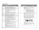
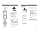
COMMUNICATION Screen
Item Functions and set values Initial value
STYLE
MACHINE ID
Settings are made for the control signal-connecting terminals on the back.
If the setting is changed, be absolutely sure to switch on the power again.
P TO P
– – –
White spot compensation is performed.
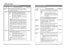
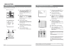
MAINTENANCE Screen
Item Functions and set values Initial value
CCD SPOT
The white spots on the screen, which are characteristic
for CCDs can be reduced.
੬ Page 42 “White Spot Compensation”
–
This sets a communication system according to the system
used.
PTOP (Point to point)
This is set when a remote control unit controls a camera.
M.DROP (Multi-drop)
This is set when a remote control unit controls a plural
number of cameras.
This is set when the STYLE item is set to M.DROP. This
is the number that identifies individual cameras in a group.
No proper function can be realized if an ID number is
repeated within a system.
A combined use with the RM-P2580 necessitates the
setting together with the video input number of the RM-
P2580.
If the item STYLE is set to P TO P, “- --” will appear, and
settings cannot be changed.
Item Functions and set values Initial value
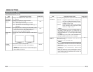
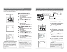
FACTORY
SETTINGS
Set values are returned to initial values.
The values set on the menu are returned to initial values.
CANCEL : No return to the initial value.
CLEAR : Returns set values except titles to the
(WITHOUT TITLE)
initial value.
CLEAR (ALL) : Returns all set values including titles
to the initial value.
Select respective set value and press the SET button.
Then, “DATA CLEARED” will appear for about 3 seconds.
Be sure not to switch off the power while the display is still
on.
MEMO
However, when FACTORY SETTINGS by means of
transmitted commands, the contents of the
COMMUNICATION menu do not return to the factory
settings.
–
FACTORY SETTINGS Screen


