


E-10
INTRODUCTION
13
[
,
,
,
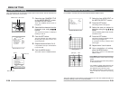
] Up-and-down, left-and-
right Button
These buttons select items on the menu
screen and change a set value.
(੬ Page 23)
14
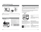
[EXT.TERM-ON/OFF] Terminal On/Off
Switch of External Synchronization
Signal
This is a terminating ON/OFF switch for
the external synchronization input signal.
When this is switched ON, termination is
executed via a 75 Ω resistor.
ON: terminates at 75Ω.
OFF: does not terminate at 75Ω.
(ON: At time of factory shipment)
15
[INT/GL, LL] Selector Switch for
Synchronizing System
This switch sets the synchronizing system
for the camera.
INT/GL:
This is set for internal synchronization
(INT) or external synchronization (GL).
LL (Line Lock):
The camera’s vertical synchronization is
locked to the AC 24V power line frequency.
When switching between multiple cameras
using a switcher, selecting this mode and
adjusting the vertical phase can reduce the
monitor sync disturbances occur that when
the camera image is switched. (This cannot
be used in regions where the power
frequency is 60 Hz ) (INT/GL: At time of
factory shipment)
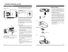
16
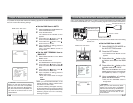
[DUPLEX, SIMPLEX] Selector Switch
for Transmission System
If the setting is changed, be absolutely
sure to switch on the power again.
DUPLEX:
This switch sets to DUPLEX when the
transmission between the camera and a
remote control unit is in a duplex system
(two-way).
SIMPLEX:
This switch sets to SIMPLEX when the
transmission between the camera and a
remote control unit is in a simplex system
(one-way).
(DUPLEX: At time of factory shipment)
17
[RX.TERM-ON/OFF] RX Signal Terminal
ON/OFF Switch
This sets whether or not the signal
between RX + and RX – on the back
20
should be terminated at the value of
110Ω resistance.
ON: Ter minated.
OFF: Not terminated.
If the system including the camera is the
M.DROP (Multi-drop, RS-485) system,
only the last camera mounted along the
control signal cable is set to “ON” and
the other cameras are set to “OFF”. In
case of the M.DROP system, it becomes
necessary to set the Machine ID. (੬ Page
33)
If the system including the camera is the
PTOP (Point to Point, RS-422A) system,
set this switch of all the cameras to “ON”.
The item STYLE on the COMMUNICA-
TION screen sets M.DROP or P TO P
(੬ Page 33)
(ON: At time of factory shipment)
18
NOT USED
This cannot be used. Do not switch.
Controls, Connectors and Indicators (Continued)
E-11
DC12V
AC24V
Y/C OUT
SYNC IN
POWER
VIDEO OUT
SEE INST-
RUCTION
MANUAL
+
-
12
CLASS 2 ONLY(U TYPE)
ISOLATED POWER ONLY
(E TYPE)
TX
+
TX
-
RX
+
RX
-
AUX
GND
A
B
CD
⁄
)
(
fi
›
¤
‹
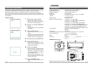
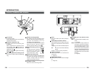
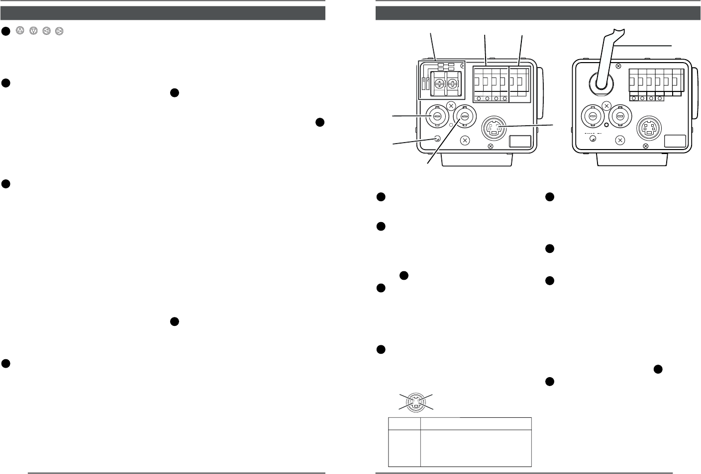
19
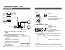
[DC 12V, AC 24V] Power input terminals
(TK-C1480BE)
To input DC 12V or AC 24V power.
20
[TX+A, TX-B, RX+C, RX-D] Control
signal connection terminals
Terminals for inputting signals with
electrical characteristics conforming to
the EIA/TIA RS-422A or RS-485 standard.
੬
17
RX.TERM switch
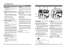
21
[AUX, GND] Auxiliary Output Terminals
If any change occurs in the area that was
set on the MOTION DETECT screen, these
terminals output signals. (੬ Page 32)
[Open-collector Low signal. Maximum
voltage 30V, Current 30mA.]
22
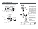
[Y/C OUT] Y/C output connector
This 4-pin connector outputs the luminance
and chrominance signal.
• Pin configuration of Y/C OUT connector
23
[VIDEO OUT] Video signal output
connector
This BNC connector outputs a composite
video signal. Connect this to the video input
connector of a video monitor, switcher, etc.
24
[POWER] Power indicator lamp
This lamp lights when power is supplied
to the camera.
25
[SYNC IN] Sync signal input connector
This BNC connector accepts the input of
an external sync signal such as a composite
video (VBS) or black burst (BB) signal.
When a sync signal is input into this
connector, the camera operation is
automatically synchronized with the
external sync signal.
To terminate this connector at 75Ω, turn
ON the EXT.TERM switch
14
.
26
Power cable (TK-C1481BEG)
Connect to the commercial AC230V
outlet
Pin No. Signal
1 GND
2 GND
3 Luminance (Y)
4 Chrominance (C)
4
2
3
1
Y/C OUT
SYNC IN
POWER
VIDEO OUT
SEE INST-
RUCTION
MANUAL
TX
+
TX
-
RX
+
RX
-
AUX
GND
A
B
CD
fl
TK-C1480BE TK-C1481BEG