


E-6
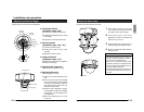
Camera unit
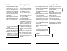
Names and Operations of Parts
3
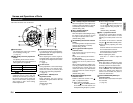
MONITOR terminal (RCA pin)
For connecting a monitor when determin-
ing camera angle, etc. (High impedance)
4
Horizontal lock screw
When adjusting the camera angles of
horizontal rotation, this screw is loosened
for adjustment and tightened to maintain
the angle.
( ੬ page 14)
5
Tilt lock screws
During adjustment of the vertical image
pickup direction of the camera angle,
loosen the screws (2 locations) and
retighten after performing adjustment.
( ੬ page 14)
6
[FOCUS ADJ. - ON/OFF] focus
adjustment switch
When adjusting the focus during
installation, setting this switch to “ON” will
open the iris.
(Default setting: OFF)
( ੬ page 14)
View when the dome cover is removed.
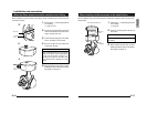
Tur ning direction of level
To darken image Counterclockwise (L side)
To brighten image Clockwise (H side)
1
Camera Head
For adjusting the angle of the camera,
such as during focusing, etc.
( ੬ page 14)
2
[IRIS LEVEL] sensitivity adjustment
volume
For adjusting the iris level of the lens.
By turning this volume, the brightness of
video signals can be adjusted.
MEMO
• When turning the level (sensitivity
adjustment) too far to the L side, the
sensitivity will increase by the AGC of
the camera and the picture quality will
reduce. For this reason, always set the
AGC switch to “OFF” when making
LEVEL adjustments.
E-7
English
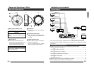
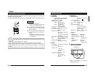
7
[AGC - ON/OFF] Auto-gain control switch
When the brightness of the subject is not
sufficient, setting this switch to “ON” will
automatically increase the sensitivity.
(Default setting: ON)
8
[BLC - ON/OFF] Backlight
compensation switch
When the subject is under backlight, setting
this switch to “ON” will open the iris and
the subject will become easier to view.
(Default setting: OFF)
9
[AUTO/MANU] Auto/manual selection
switch
For selecting whether to adjust the white
balance automatically or manually.
(Default setting: AUTO)
10
[INT/LL] Synchronization system
selection switch
This switch sets the synchronizing
system for the camera.
INT:
This is set for internal synchronization
LL (Line Lock):
The camera’s vertical synchronization is
locked to the AC 24 V power line fre-
quency.
When switching between multiple cam-
eras using a switcher, selecting this mode
and adjusting the vertical phase can
reduce the monitor sync disturbances
occur that when the camera image is
switched.
(Default setting: INT)
11
[WHT.BAL/PHASE] adjustment
selection switch
Switch to select the function of the
12
[R/B. +/-] adjustment button.
Ⅲ When setting to WHT.BAL:
When the
9
[AUTO/MANU] switch is
set to MANU, the white balance can
be adjusted using the [R/B, +/-] button.
Ⅲ When setting to PHASE:
When the
10
[INT/LL] switch is set to
LL, the vertical phase of the line lock
can be adjusted using the [R/B, +/-]
button.
(Default setting: WHT.BAL)
12
[R/B, +/-] adjustment button
This button is pressed when manually
adjusting the white balance or when
adjusting the vertical phase of the line
lock.
The function of this button is selected
using the
11
[WHT.BAL/PHASE] switch.
Ⅲ When manually adjusting the white
balance:
Press the R button to increase the red
tint and decrease the blue tint.
Press the B button to increase the blue
tint and decrease the red tint.
Ⅲ When adjusting the phase:
Press the + or - button to adjust the
phase.
13
[RESET] Reset button
When this button is pressed, the value
of the white balance or phase adjusted
manually is reset to the default value.
When the
11
[WHT.BAL/PHASE] switch
is set to WHT.BAL, the white balance is
reset to the default value. When the
switch is set to PHASE, the phase is
reset to the default value.
14
[SPOT CORRECTION] White-spot
correction button
When this button is pressed, white spots
are corrected.
( ੬ page 18)