


E-12
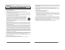
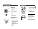
Ⅲ Video signal cables
Connect the coaxial cables to the coaxial
cable processing terminal.
Note
Use the RG-59 or RG-6 video signal cable
(coaxial cable). The RG-11 cannot be
used.
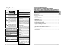
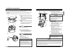
Connect the Cables to the Base
• Perform the process shown on the left
diagram (above illustration) for the
coaxial cable tip before connecting.
Ⅲ DC 12 V or AC 24 V power supply cable
Connect a DC 12V or AC 24V power supply
cable to the power supply terminal. To pre-
vent connection errors or a cable disconnec-
tion, we recommend the use of lug plates for
the connections.
The following table shows the connection dis-
tances and connection cables provided that
2-conductor VVF cables (vinyl-insulated vi-
nyl sheath cables) are used.
Maximum extension
Conductor
diameter
100 m 260 m 410 m 500 m
(330ft) (850ft) (1300ft) (1640ft)
q
1.0mm
q
1.6mm
q
2.0mm
q
2.6mm
(AWG18) (AWG14) (AWG12) (AWG10)
• Do not allow input from both a DC 12 V
and AC 24 V power supply at the same
time.
• When using a DC 12 V power supply,
ensure that the polarities of the cable
are correct.
• The AC 24 V power supply should
conform to the following:
U-type: Class 2 only
E-type: Isolated power supply only
CAUTION:
• If thin cables are used (i.e. with a high
resistance), a significant voltage drop
will occur when the unit is at its
maximum power consumption. Either
use a thick cable to restrict the voltage
drop at the camera side to below 10%,
or place the power supply near to the
camera. If voltage drop occurs during
operation, the performance will be
unstable.
• Attach the cable conductors so that they
do not come into contact with the safety
cable.
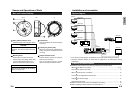
Power Supply
terminal
DC 12 V or AC 24 V
Power Supply cable
Coaxial
cable
processing
terminal
Coaxial cable
Installation and connection
Connect the coaxial cables and power supply cable to the terminals within the Base.
•Turn OFF the power supply to all compornents before making connections.
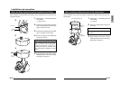
Fold back the net and insulate so that a short cir-
cuit does not occur from the net coming apart.
Net
Insulation tape
Polyethylene
Core line
12mm 5mm
(
15
/32"
)(
3
/16"
)
E-13
English
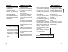
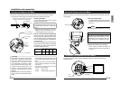
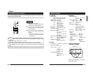
Ⅲ Fill using sealing agent
Completely fill the conduit hole using seal-
ing agent. Also fill the mounting holes when
not in use.
MEMO
The sealant should be GE silicone or equal.
Ⅲ Mount the camera unit to the base
Fit the camera unit within the base and
securely fasten the screws in the order of
ᕃ and ᕄ.
Mount the Camera unit to the Base
Sealing agent
CAUTION
Not filling the holes completely with seal-
ing agent may cause moisture to enter,
clouding the lens and dome cover as a
result. Be sure to completely close the
holes.
Mount the camera unit to the base after filling the conduit hole and mounting holes with
sealing agent.
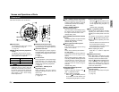
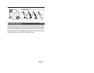
Connection for Adjustment of the Camera
Temporarily used for making various adjustments while the camera remains in the
installed location.
IRIS
LEVEL Volume
751 termination
disconnected
Adjustment
button
Setting switch
Monitor TV
ᕃᕄ