


E-9
English
REC
PLAY
FF
REW
REVERSE
PAUSE/
STILL
REC
CHECK
STOP/EJECT
COUNT/
CLOCK
TIME
MODE
TIMER
REC
AL/PL
RESET
MENU
VIDEO CASSETTE RECORDER
SHIFT/TRACKING
SET/V.LOCK
RESET
/CANCEL
OPERATE
SR-L910E
OPE. LOCK
1
TO CAMERA
TO CAMERA
DATA I / O
DATAI/O
RX
RX
+
RX
RX
-
TX
+
TX
-
COM
COM
1 2 3 4 5 6 7 8
COM
COM
9/1
9/1
10/2
10/2
11/3
11/3
12/4
12/4
13/5
13/5
14/6
14/6
15/7
15/7
16/8
16/8
COM
COM
COM
COM
COM
COM
CAMERA
CAMERA
SW
SW
UNIT
UNIT
ALARM
ALARM
AUTO
4312 8756
2 3 4 5 6 7
8
1
MONITOR
MONITOR
OUTPUT
OUTPUT
MONITOR
MONITOR
SERIAL-2
SERIAL-2
SERIAL-1
SERIAL-1
VIDEO INPUT
VIDEO INPUT
VIDEO OUTPUT
VIDEO OUTPUT
OUTPUT
OUTPUT
2
1
ON
2 3 4 5 6 7
8
POWER
OFF
ON
AC INPUT
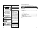
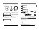
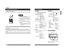
System diagram
Installation and connection
•Turn OFF the power supply to all equipment to be used before making connections.
• Read the Instruction Manual for each piece of equipment to be used before making
connections.
Camera 1
Video signal
Power
Camera 2
Video signal
Power
Camera 3 Video signal
Power
Camera 4
Video signal
Power
Power Unit
DC 12 V or AC 24 V
TO
CAMERA
Switcher, etc.
MONITOR
OUTPUT 1
MONITOR
OUTPUT 2
MONITOR
MONITOR
DVR, etc.
VIDEO IN
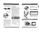
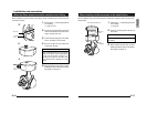
Ⅲ Install the dome camera to the ceiling by following the procedure below
• Mounting the Base to the Ceiling ........................................................................... 10-11
=
• Connect the Cables to the Base ................................................................................. 12
=
• Mount the Camera unit to the Base ............................................................................ 13
=
• Connection for Adjustment of the Camera.................................................................. 13
=
• Adjusting the Camera Angle ....................................................................................... 14
=
• Attach the Dome cover................................................................................................ 15
Ⅲ When the Dome camera cannot be installed to the Ceiling ........................................ 16
Ⅲ When installing the Dome camera to the electrical box .............................................. 17
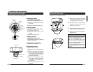
Installing the Dome camera
E-8
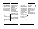
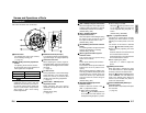
1
Safety cable installation screw
Install the safety cable using this screw.
2
Mounting holes
These holes are used to mount the
camera body to the ceiling. When using
a 4 inch square electrical box, the 2
holes are used to fix the box in place.
3
Conduit hole
Hole for installation to conduit hole pipe
and wiring.
4
Conduit plug & hole (side)
When the unit cannot be installed to the
ceiling, the pipe is mounted to this hole
for wiring.
5
Tamper-resistant screws
Tamper-resistant screws for fixing the
dome cover to the base.
Use the provided wrench to install/
remove the Tamper-resistant screws.
Names and Operations of Parts
Main unit bottom/side/top
CAUTION
Be sure to attach the safety cable. If not
attached, the camera body could drop
down.
sidebottom top
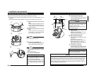
CAUTION
Use screw size suitable for the mounting
holes (4.4mm(
11
/64")).
121mm
(4
3
/4")