14
Cable Connections
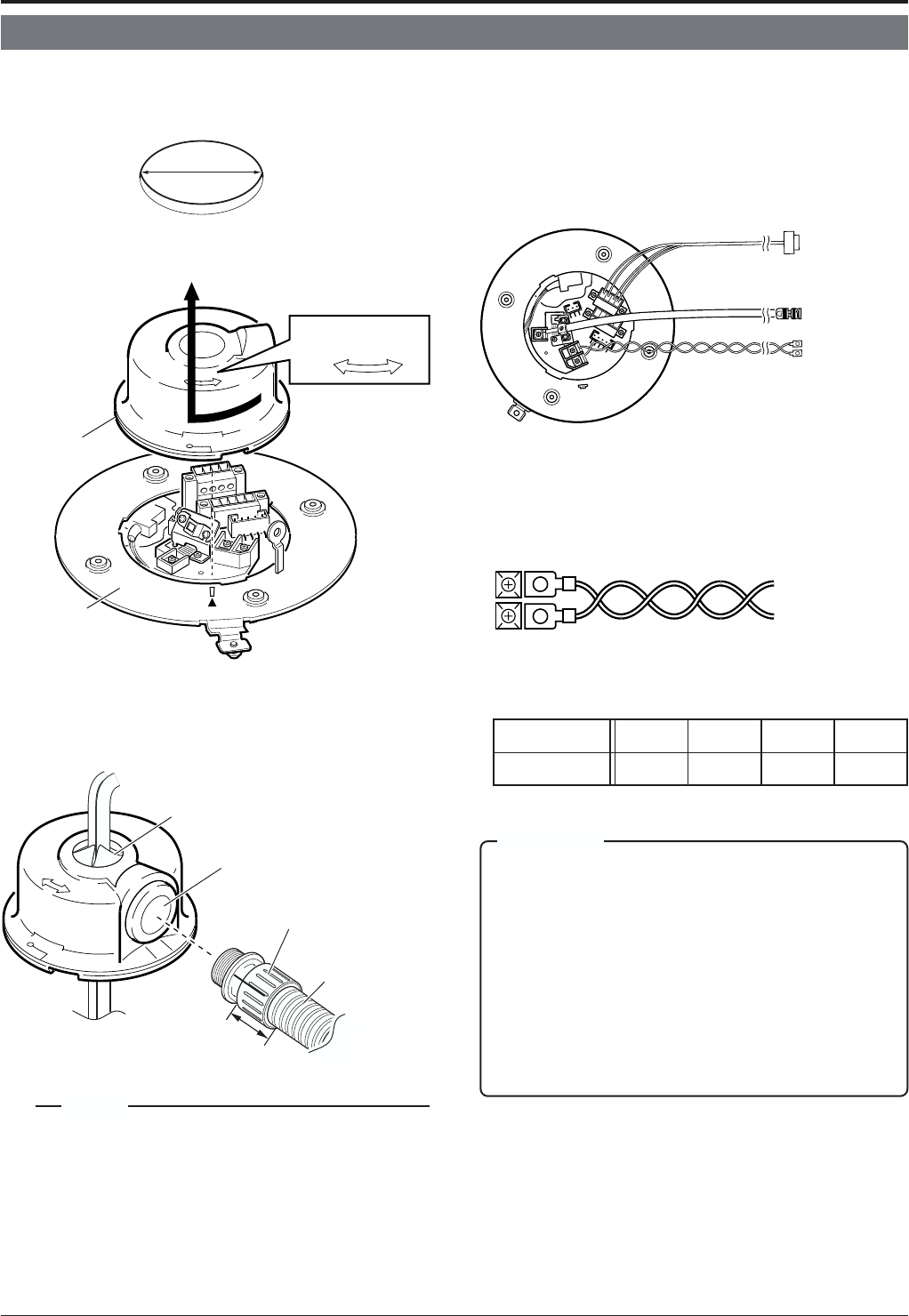
Connect cables to the Ceiling Mount as described below.
1.
Make a 90 mm diameter hole in the ceiling.
4.
Connect the cables.
Connect the cables to the terminals on the Ceiling Mount.
The four connections consist of a AC 24V power cable, a
coaxial cable and a control signal cable.
2.
Remove the cover from the Ceiling Mount.
3.
Pass the cables through the cover.
Make slits in the rubber cap on the cover as shown in the
diagram below. Pull the cables through the hole in the
ceiling and pass the cables through the slits.
Diameter 90 mm
Cover
Ceiling Mount
RELEASE LOCK
Cap (Side)
Tube
Maximum diameter
22 mm
Cap (Top)
Drip-proof pipe
33 mm or less
Connector
Maximum diameter 31 mm
Power cable
Control signal cable
To a remote controller
such as RM-P2580
To the monitor, etc.
To the AC 24 V
power supply
AC 24V power cable
This cable connects the AC 24V power supply to the AC
24V input connector. To prevent connection errors and
disconnections, the use of lug plate for connections to the
AC 24 V INPUT connector is recommended.
When a 2-conductor VVF (Vinyl-insulated vinyl-sheath ca-
ble) is used, the maximum connection length is as shown
below. (These are merely the standard reference values.)
Maximum cable length
100 m 260 m 410 m 500 m
Wire diameter (mm) 1.0 or more 1.6 or more 2.0 or more 2.6 or more
Connections & Installation
CAUTIONS
● When thin cables are used the cable resistance increases. As
a result, when the power consumption of the unit is at its max-
imum level (during the simultaneous operation of panning and
tilting) the effective voltage will drop.
When the voltage drops while the camera is in use, perform-
ance can become unstable and preset positions may not be
reproduced accurately.
To prevent problems, either use thicker cables that have lower
resistance or decrease the cable length by installing the power
supply unit closes to the camera. Attempt to reduce the volt-
age drop to less than 10% while the rated current level of the
camera is flowing through the cable.
● Do not connect an AC 24V cable directly to an AC 230 V outlet.
This will cause damage to the unit.
MEMO
The diameter of the cover hole without the cap is 20.5 mm.
For dust prevention, remove the cap (side) and install a
drip-proof pipe.
(Be sure to use a drip-proof pipe. The maximum diametre
of the pipe connector is 31 mm.)
When distributing the cable from the side, use JVC’s WB-
S573 ceiling direct-mount bracket. In this case, the length
of the connector should be 33 mm or less, and the maxi-
mum diameter of the tube should be 22 mm or less.


