17
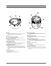
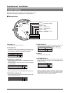
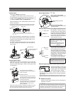
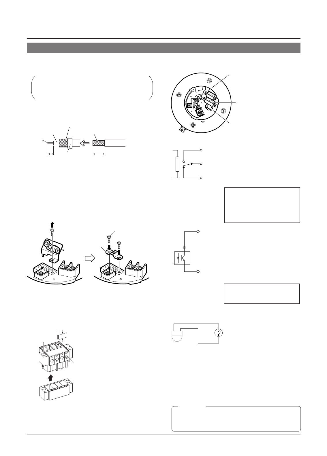
Alarm input/output terminals
(CN23)
Alarm input terminals (CN26)
Connect the provided 6P Alarm cable
to these terminals.
Alarm output terminals (CN24)
Connect the provided 4P Alarm cable
to these terminals.
Mesh wiresPolyethylene
The figures inside the brackets ( ) are the dimensions
when the coaxial cable is distributed from the side of the cover.
(Unit : mm)
Conductor
wire
7
(5)
17
(12)
Insulation tape
Fold back the mesh wires and secure them with insulation tape in order
to prevent them from becoming loose and thus causing a short circuit.
If the cable is extended, the signal attenuation is increased,
the resolution drops and the noise increases. Should it be
required to extend the cable, use a thicker cable or a ca-
ble length compensator.
To lead the coaxial cable through the cap on the side of
the cover, change the positioning of the cable plate as
shown below.
Provided screw
Provided cable
plate
Screw removed in the
figure on the left
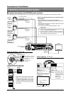
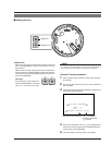
Control signal cables
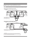
RM-P2580 units allow the connection of up to eight cam-
eras to a single set of control signal cables. The overall
maximum permissible length of these control signal cables
is 1200 meters.
Alarm signal cables
☞
P. 8
5.
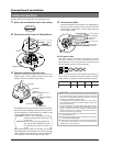
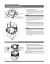
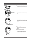
Attach the cover.
Attach the cover to the ceiling mount by reversing the
operations in step
2
.
Coaxial cable
Connecting a RG-59 coaxial cable.
If a RG-11 coaxial cable is used it cannot be con-
nected directly to the terminal board. To use such a
cable, connect a RG-59 cable to the camera and then
connect the RG-11 cable to the RG-59 cable.
Treat the extremity of the coaxial cable as shown below
before connecting it.
Flat-blade
screwdriver
Cable
4 mm
Flat-blade screwdriver
The connector can be released by
loosening the screws on the two sides as
shown in the figure.
Strip the coating of each cable by about 4
mm before inserting it. After connecting all
of the cables, turn the screws on the side
to fasten the connectors.
It is recommended to use a 4-core (a pair)
twisted pair cable (0.65) or a twisted pair
cable of category 3 or higher which is
used for a Ethernet.
Cables with a thickness between 16 AWG and 26 AWG can be used.
Connect the control signal cables so that the TX+ and TX- signals
form a pair and the RX+ and RX- signals form another pair.
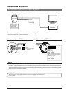
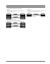
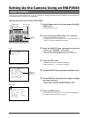
Electrical Specification of the Alarm Output Terminals
• The ALARM 1 terminal outputs a
contact signal. In the alarm status,
the section between N.OPEN and
COM is shorted (makes an electri-
cal contact) and the section be-
tween N.CLOSE and COM is
opened (breaks contact).
Rating
Maximum applied voltage: 30 V
DC or 24 V AC
Maximum applied current: 2 A
Contact life: 200,000 times of
operation
N. OPEN
N. CLOSE
COM.
• The ALARM 2 and ALARM 3 ter-
minals output open-collector sig-
nals insulated by photocouplers.
The terminal is ON in the alarm status.
As these terminals are provided
with polarity, make sure that the
voltage at the + terminal is higher
than that at the – terminal.
Do not apply inverse voltage to pre-
vent damage of these terminals.
Rating
Maximum applied voltage: 20 V DC
Maximum drive current: 25 mA
ALARM2+
or
ALARM3+
ALARM2–
or
ALARM3–
22 1
Electrical Specifications of Alarm Input Terminals
ALARM1
GND
•To prevent penetration of noise in the
internal circuitry, apply a non-voltage
contact signal to the ALARM input
terminal. Never apply a voltage.
• Use the appropriate menu to select whether the alarm is
identified by shorting (making contact) or by opening (break-
ing contact).
• Apply an alarm signal for at least 200 ms. If it is shorter, it is not
guaranteed that the signal will be recognized as an alarm signal.
CAUTION
In order to prevent foreign objects from entering inside the ceiling
mount be sure to attach the hemispherical cover correctly. The
penetration of foreign objects into the ceiling mount may cause a
malfunction and smoking or in the worst case a fire ignition.


