


4 KODAK VISION Premier Color Print Film / 2393
™
• H-1-2393t
Sound-Track Printing
Analog and digital sound-track printer setup and control
procedures for KODAK VISION Premier Color Print
Film / 2393 are similar to Film 2386 / E / 3386 / E, with
little or no change required.
Analog variablearea positivesound tracks ofsilver plus
dye usually restrict the exposure to the top two emulsion
layers by inserting KODAK WRATTEN Gelatin Filters
No. 12 and No. 2B
*
in the light beam. The optimum
variable-area sound-track density for the print is between
1.1 and 1.8 (read at 800 nm). You can achieve excellent
frequency response and a high signal-to-noise ratio in this
density range.
Note: With the same soundtrack negative, the print
density of VISION Premier Color Print Film / 2393 is
about .1 higher than VISION Color Print Film / 2383.
For a variable area positive sound track of silver plus
magenta dye only, printed from a negative sound track,
restrict the exposure to the top two emulsion layers by
inserting KODAK WRATTEN Gelatin Filter No.12 and
KODAK Color Compensating Filter 110 Cyan in the light
beam. The optimum variable-area sound-track density for
the print is between 0.8 and 1.1 (read at 800 nm). This
print density will provide a good compromise between
signal-to-noise ratio and frequency response.
Use cross-modulation test procedures to determine the
density of the sound-track negative required to produce
minimum cross-modulation distortion at the optimum
print density.
Digital sound-on-film soundtracks (e.g., Dolby Digital
and Sony SDDS) are dye only. Consult the system vendor
for performance recommendations.
SPLICING
Use tape splices for this film. Since ESTAR Base is
impervious tomost solvents,cement spliceswill not work.
Keep the knife on the tape splicer sharp and properly
aligned with the splicer platen. As the knife is lowered to
cut the film, slight leftward pressure will help ensure a
tight mesh of the cutting edges to give a clean cut. Taping
both sidesof the filmis recommended tominimize fold-up
or stretching. An ultrasonic weld splicer (Metric splicer)
also may be used.
You can use tape splices to intercut triacetate and
ESTAR Base film. However, because ESTAR Base prints
are 20 micrometres thinner, there may be a slight focus
difference when projecting on a large screen. To assure
compatibility, order the same type of film stock for all
prints used in a production.
* You can omit the No. 2B Filter without affecting the sound quality.
Using this filter is an operational convenience to
conform with printer setup for other products that require it.
STANDARD PRODUCTS AVAILABLE
Note: For availability of non-standard products, contact
your Kodak location.
IMAGE STRUCTURE
This film’s excellent sharpness captures the detail in the
printing negative for projection onto the largest of theatre
screens. Fine-grained emulsions, an ultra-thin layer
structure, intragrain absorbing dyes, and superior halation
protection contribute to its performance.
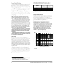
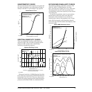
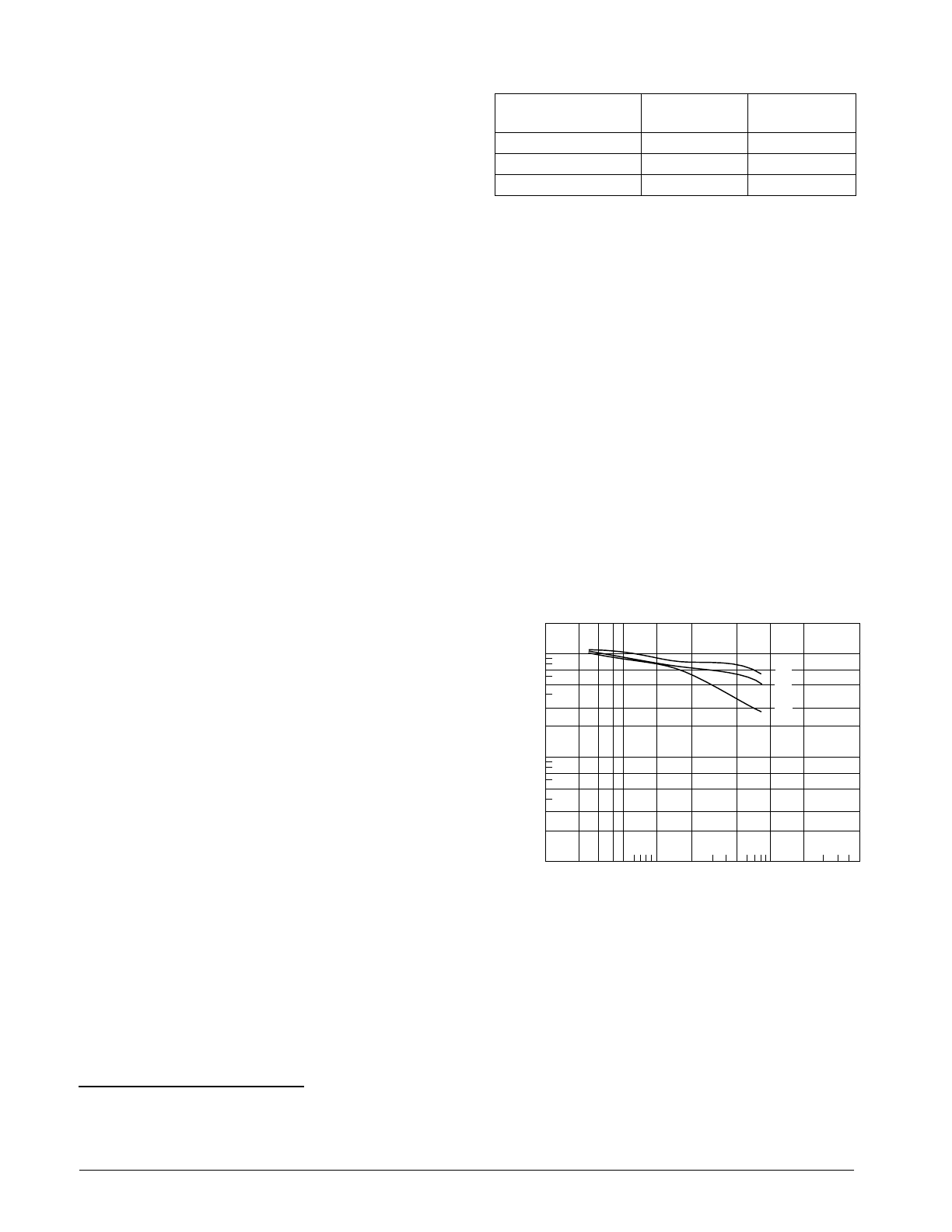
MODULATION-TRANSFER CURVE
This graph shows a measure of the visual sharpness of this
film. Thex-axis, “Spatial Frequency,” refers tothe number
of sine waves per millimetre that can be resolved. The
y-axis, “Response,” corresponds to film sharpness. The
longer and flatter the line, the more sine waves per
millimetre that can be resolved with a high degree of
sharpness — and, the sharper the film.
Modulation-Transfer Curves
Format
Length in Feet
(Metres)
Perforation
Pitch
35 mm SP666 2000 (610) KS-1870
35 mm SP779 4000 (1220) KS-1870
35 mm SP789 6000 (1829) KS-1870
F010_0058AC
1001 2 3 4 5 10 20 50 200 600
SPATIAL FREQUENCY (cycles/mm)
RESPONSE (%)
10
1
2
5
3
7
30
20
100
70
50
200
R
G
B