


13
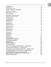
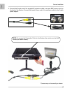
Back Panel
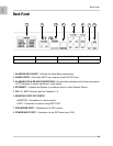
Back Panel
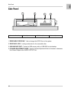
1. ALARM BLOCK CHART - Outlines the Alarm Block connections
2. AUDIO PORTS - One Audio INPUT port, and one Audio OUTPUT port.
3. ALARM BLOCK & RS-485 CONNECTIONS - Controls Alarm devices, and for direct connection
to PTZ cameras. 4 sensor inputs and 1 relay output.
4. ETHERNET - Connects the System to a network router or other Ethernet Device.
5. CH 1~4 - BNC Camera inputs for Channels 1~4.
6. MONITOR / SPOT OUT PORTS:
• MONITOR - Connection to a slave monitor.
• SPOT- Connection to monitor using SPOT OUT.
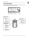
7. PS/2 MOUSE PORT - Connection for a PS/2 mouse
8. POWER INPUT PORT - Connection for the DC Power Input (12V).
1
2
3
4 5
1. Alarm Block Chart
6. Monitor / Spot Out Ports
2. Audio Ports
5. CH 1~4
3. Alarm Block & RS-485
7. PS2 Mouse Port
4. Ethernet Port
8. Power Input Port
6
7
8