


3
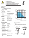
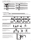
4. Selecting a Location
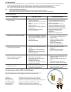
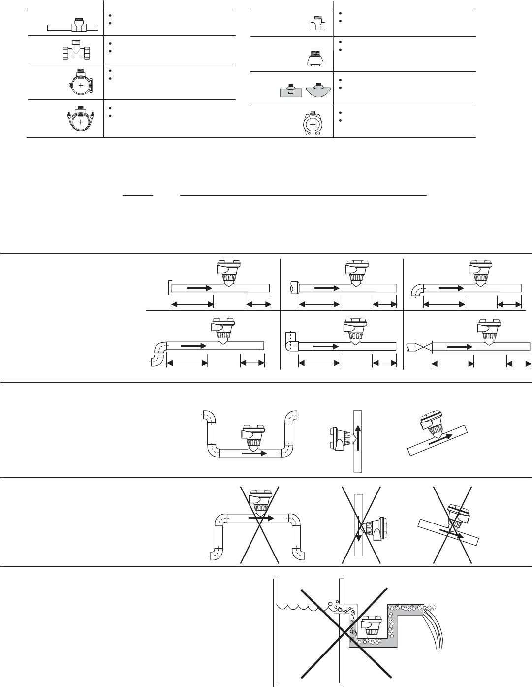
• The FMG-3000 requires a full pipe and a fully developed turbulent fl ow profi le for accurate measurement.
• If the piping system harbors air pockets or bubbles, take steps to locate the sensor so the air pockets will not contact the
electrodes.
• In vertical installations, assemble the unit so the conduit ports are facing downward. This prevents condensation inside the conduit
from being directed into the electronics housing.
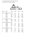
15 x I.D. 5 x I.D.
Reducer
+
GF
+
10 x I.D. 5 x I.D.
Inlet Outlet
Flange
+
GF
+
50 x I.D. 5 x I.D.
Valve/Pump
+
GF
+
40 x I.D. 5 x I.D.
2 x 90° Elbow
3 dimensions
+
GF
+
25 x I.D. 5 x I.D.
2 x 90° Elbow
+
GF
+
20 x I.D. 5 x I.D.
90° Elbow
+
GF
+
+
G
F
+
+
GF
+
+
GF
+
+
GF
+
+
G
F
+
+
GF
+
O.K.O.K. O.K.
Vertical flow is OK IF the pipe remains full at all times.
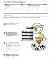
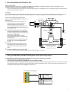
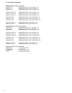
3. Installation: Pipe fi ttings
Omega offers a wide selection of installation fi ttings that control the position of the Magmeter electrodes in relation to the dimensions of
the pipe. You will fi nd a complete list of order numbers for installation fi ttings in the Calibration tables on pages 9-13.
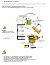
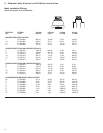
Select a location with suffi cient
distance of straight pipe immediately
upstream of the sensor.
Locating the sensor in a trap or where the
fl ow is upward helps to protect the sensor
from exposure to air bubbles when the
system is in operation.
NOTE: The system must be designed to
keep the sensor wet at all times.
These confi gurations are not
recommended because it is diffi cult to
keep the pipe full.
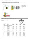
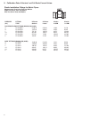
Type Description
2 to 4 inch, cut 1-7/16 inch hole in pipe
Over 4 inch, cut 2-1/8 inch hole in pipe
0.5 to 4 inch versions
PVC or CPVC
2 to 4 inch, cut 1-7/16 inch hole in pipe
6 to 8 inch, cut 2-1/8 inch hole in pipe
Iron, Carbon Steel,
316 SS Threaded
tees
Carbon steel &
stainless steel
Weld-on
Weldolets
2 to 4 inch, cut 1-7/16 inch hole in pipe
Over 4 inch, cut 2-1/8 inch hole in pipe
For pipes DN 65 to 200 mm
PP or PVDF
For pipes from DN 15 to 50 mm
PP or PVDF
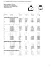
Type Description
Plastic tees
Metric
Wafer Fitting
Metric
Union
Fitting
PVC
Saddles
Iron
Strap-on
saddles
1.5 in. to 8 in. PVDF insert
> 8 in. PVC insert
Fiberglass
tees &
saddles:
FPT
FPS
0.5 to 2 in. versions
Mounts on threaded pipe ends
In a gravity-fl ow system, the tank must be designed
so the level does not drop below the outlet.
This causes the pipe to draw air in from the tank.
If air bubbles pass across the Magmeter electrodes,
the output will become erratic.
+
GF
+