


5
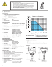
6. General Installation and Grounding Tips
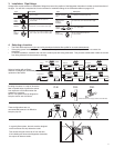
Sensor conditioning
The Magmeter output signal may be unstable immediately after installation. Allowing the sensor to soak in a full pipe (or in any
container of water) for 24 hours will stabilize the performance.
• Very low conductivity fl uids may require a longer conditioning period. (The Magmeter may not operate properly in fl uids where the
conductivity is less than 20 µS/cm.)
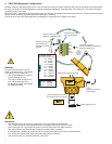
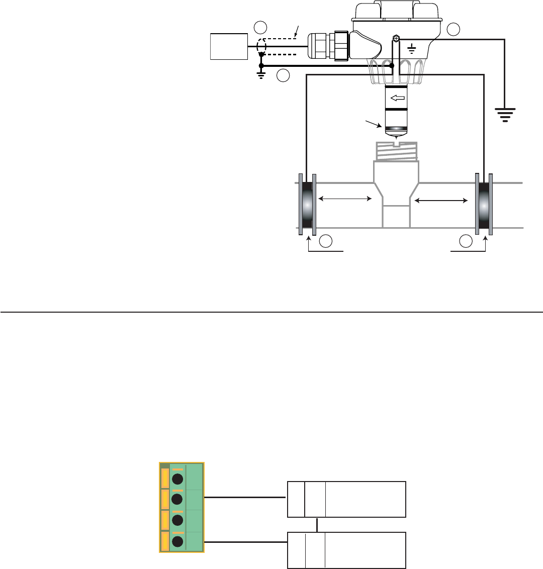
Grounding
The FMG-3000 Magmeter is unaffected by moderate levels of electrical noise. However, in some applications it may be necessary to
ground portions of the system to eliminate electrical interference. The grounding requirements will vary with each installation.
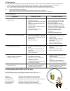
One or more of the following steps may be
applied if the FMG-3000 Magmeter is affected by
electrical noise:
The ground terminal on the outside of the
yellow housing is connected internally
to the grounding ring at the tip of the
sensor. Connect a wire (14 AWG/1.5 mm
2
recommended) from this terminal directly to a
local Earth ground.
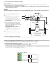
Install fl uid grounding devices immediately
upstream and downstream of the Magmeter.
Connect the fl uid grounds to the Earth ground
terminal on the FMG-3000.
Use fl anged grounding rings or metal
electrodes on plastic pipes, or metal clamps
on metal pipes.
Fluid grounds must be in direct contact with
the fl uid, and as near to the Magmeter as
possible.
The shield from the output cable must be
terminated at the remote instrument ONLY.
This shield must not be connected at both
ends!
Connect an additional wire (minimum AWG
14/1.5 mm
2
) from the remote instrument ground to the Magmeter ground terminal.
Grounding rings on plastic pipe
(Install between flanges)
or
metal straps on metal pipe
Earth ground
Sensor
Grounding ring
(10 cm to 1.3 m)
(10 cm to 1.3 m)
4 in. to 50 in.
4 in. to 50 in.
Instrument
4.
1.
2.2.
Do not terminate
shield at Magmeter
3.
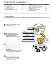
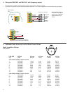
7. Wiring the FMG-3002 and FMG-3102 Magmeter with 4-20 mA Loop Output
The FMG-3002 and FMG-3102 Magmeters are traditional 2-wire passive 4-20 mA loop transmitters.
• External loop power (24 VDC ±10%) is required.
• The maximum loop resistance the Magmeter can accomodate is 300 Ω.
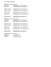
• All FMG-3002 and FMG-3102 Magmeters are shipped from the factory with the 4-20 mA output scaled for 0 to 5 m/s (0 to 16.4 ft/s).
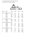
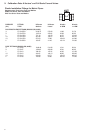
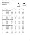
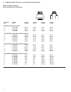
The Calibration charts on pages 6-10 list the 20 mA setpoint for each installation fi tting. Use this information to program the 4-20
mA range of the loop device (PLC, Datalogger, recorder, etc.)
1
2
3
4
Loop + (24 VDC)
Loop - (Ground)
4-20 mA Loop
monitor
(Maximum 300 Ω)
FMG-3000 Series Magmeter
+
+
-
-
24 VDC ± 10%