


40
Chapter 4
Adjustments and settings for recording
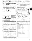
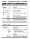
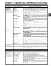
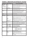
Display item What is displayed Status when display appears
8 Cumulative gain
display
6:/12:/20:
This indicates the value of the cumulative gain (DS.GAIN) when this
gain function is working.
9 Gain value ¢¢dB
This indicates the current gain value.
7WHITE BAL switch
position
A
B
P
T
This indicates that the WHITE BAL switch is set to channel A.
This indicates that the WHITE BAL switch is set to channel B.
This indicates that the WHITE BAL switch is set to PRE.
This indicates that the ATW mode has not been set. It flashes when the
brightness and color are outside the operating range.
6 Filter positions
1 to 4
A to D
–
This indicates the position of the ND filter.
This indicates the position of the CC filter.
This indicates that the filter has not been set to a proper position.
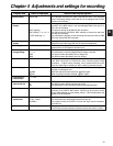
5 Information
allocated to USER
buttons
UM: USER MAIN
U1: USER1 button
U2: USER2 button
REC SW
Y GET ON
RET SW
ATW ON/OFF
D.ZOOM ON/OFF
This appears only during MODE CHECK button operations while the
USER button functions as the REC switch.
This appears when the function for measuring the output brightness level (in
% units for approx. 3 seconds for the area near the center marker) is ON.
This appears only during MODE CHECK button operations while the
USER button functions as the RET switch.
This appears when ATW is operating.
This indicates whether D.ZOOM is set to ON or OFF.
; AUDIO input
system and level
meter
This indicates the audio channels selected and their audio levels.
This appears when the AUDIO IN switch is at the FRONT position.
This appears when the AUDIO IN switch is at the WIRELESS position.
This appears when the AUDIO IN switch is at the REAR position.
---- ---+
∫
: VTR warnings,
information
REC WARNING
SLACK E-¢¢
HUMID
SERVO
RF
BACKUP BATT EMPTY
WIRELESS-RF
This indicates that a problem has occurred during recording.
This indicates that a problem has occurred in a mechanism. Depending on the
nature of the trouble concerned, the power may be turned off automatically.
<Note>
For details on the codes displayed in this area, refer to “6-3-2 Error codes.”
This indicates that condensation has formed.
This indicates that servo lock has not been initiated during recording or
playback.
This indicates that the level of the signals from the tape has dropped.
This signals that it is time to replace the backup battery.
This indicates that the level of the RF signal from the wireless
microphone receiver has dropped.
=Iris override
display
++
+
(No display)
–
– –
When the iris override function is working, this indicates how much
compensation is provided.
++: The aperture is opened by a full stop.
+: The aperture is opened by a half stop.
– –: The aperture is closed by a full stop.
–: The aperture is closed by a half stop.
No display: Reference status
< Time code display
TCG 12:59:59:20
TCR 12:59:59:20
(V)UBG
AB CD EF 00
(V)UBR
12 34 56 78
CTL –01:59:59:20
This indicates the TCG (time code generator) value.
This indicates the TCR (time code reader) value.
This indicates the UBG VUBG display.
This indicates the UBR VUBR display.
This indicates the CTL-COUNTER value.
F
W
R
> Iris, f-value
NC
OPEN
F1.7 to F16
CLOSE
This appears when the lens cable is not connected.
This appears when the lens aperture is open.
This indicates the aperture value (f-value) of the lens.
This appears when the lens aperture is closed.
<Note>
These displays appear when using a lens equipped with an aperture
value display function. They flash while the aperture is being changed
for the iris override.