


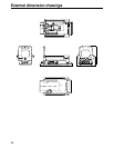

4
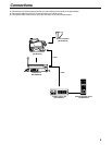
Controls and their functions
1
2
3
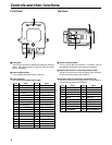
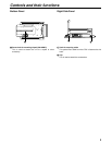
1 Lens guide
The 2/3z box-type lens is attached by hooking it onto this
guide. Align the guide pin of the lens with the center
groove, and attach.
2 Lens anchoring knob
This is rotated clockwise to anchor the lens.
3 Lens connector
Lens connector (57-20360 made by DDK)
Front Panel
5
4 6
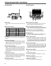
4 Camera mounting base
This is used to attach the camera. For details, refer to
the operating instructions of the camera concerned.
5 Optical fiber cable for connecting camera [CAM]
Use this to connect the unit to the optical fiber connector
on the multi-format camera (AK-HC931P).
6 Interface cable for connecting camera [EXT I/O]
Use this to connect the unit to the EXT I/O connector on
the multi-format camera (AK-HC931P).
Top Panel
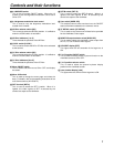
Pin No.
1
2
3
4
5
6
7
8
9
10
11
12
13
14
15
16
17
18
Signal
N.C.
N.C.
N.C.
DC +12V
POWER GND
SIGNAL GND
DOBY GND
EXT. MODE (A)
EXT. MODE (B)
EXT. MODE (C)
16:9/4:3 SEL
IRIS POSITION
ZOOM POSITION
RET1
RET2
FOCUS POSITION
IRIS CONTROL
IRIS AUTO/REMOTE
Pin No.
19
20
21
22
23
24
25
26
27
28
29
30
31
32
33
34
35
36
Signal
N.C.
N.C.
TALLY CONT1
N.C.
N.C.
LENS CODE (A)
LENS CODE (B)
LENS CODE (C)
LENS CODE (D)
EXT CONT A
EXT CONT B
N.C.
INCOM1 PROD/ENG
I
NCOM2 PROD/ENG
INCOM1 SW
INCOM2 SW
N.C.
N.C.
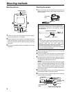
Pin No.
1
2
3
4
5
6
7
8
9
10
Signal
BU ACTIVE
ANALOG GND
RET-1
RET-2
RET-3
DIGITAL GND
CAMERA DATA
CAMERA CONTROL
DC +12 V
POWER GND
Pin No.
11
12
13
14
15
16
17
18
19
20
Signal
MONITOR SIGNAL
MONITOR GND
DC +5 V
DC +3.15 V
DC +2.7 V
IRIS CONTROL
IRIS POSITION
ZOOM POSITION
FOCUS POSITION
IRIS AUTO/REMOTE