- 11 (E) -
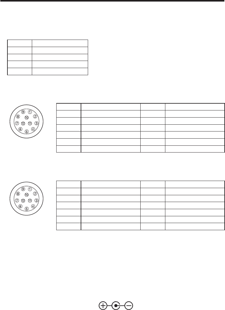
Tally output connector [TALLY OUT]
The R tally and G tally signals are output from this connector.
These signals take effect when the optional card for studio applications has been
inserted.
Pin No. Signal
1 GND
2 R_TALLY_OUT
3 G_TALLY_OUT
4 +12 V (500 mA Max)
IRIS connector [IRIS]
Used to connect the IRIS control cables of the lens.
Pin No. Signal Pin No. Signal
1 Return control 7 Iris follow
2 VTR-S/S 8 Iris auto selection
3 UNREG GND 9 —
4 Iris manual selection 10 Zoom position information
5 Iris control 11 Focus position information
6 UNREG 12 V 12 NC
Zoom/Focus connector [ZOOM/FOCUS]
Used to connect the zoom/focus control cables of lens.
Pin No. Signal Pin No. Signal
1 Focus control selection 7 COM
2 Zoom control selection 8 Focus control
3 GND 9 Zoom control
4 Forcible iris closing 10 Iris control selection
5 Iris control 11 COM +Voltage
6 +Voltage 12 COM –Voltage
Operate indicator
Green LED lamp lights to indicate that the specified DC power is supplied to
the DC 12 V input connector
.
When the video format is changed, the operate LED flashes twice when the format is
720/60p and once with any other format.
DC 12 V input connector [DC12V IN]
12 V DC is supplied through the optional DC power supply cable (AW-CA4T1).
Major operating controls and their functions


