


10
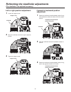
Controls and their functions
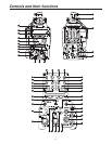
Monitor output selector switch [MONI SEL]
This is used to select the images (Y, NAM, R, G, B) which
are to be output from the monitor output connector.
ND filter selector knob
This is used to adjust the optical filter manually when
LOCAL has been selected as the filter setting.
1:
CAP, 2: Through, 3: 1/4, 4: 1/16, 5: 1/64
CC filter selector knob
This is used to adjust the optical filter manually when
LOCAL has been selected as the filter setting.
A:
3200K, B: 4300K, C: 6300K, D: Cross, E: DF0
Gain selector switch [GAIN]
This is used to select the gain for the camera images.
It is not effective when the CCU is connected to the
camera.
Camera output selector switch [OUTPUT]
This is used to select the video output (CAM, BAR or
TEST).
It is not effective when the CCU is connected to the
camera.
White balance memory selector switch [W.BAL]
This is used to select the white balance memory.
Data can be recorded in A or B.
The factory settings are established when the switch is
set to PRST.
It is not effective when the CCU is connected to the
camera.
Assignable switch [USER 1, 2, 3]
Using the setting menu, user settings can be assigned to
this switch.
SD card connector [SD CARD]
The SD card (optional accessory) is inserted here.
For the recording items, refer to the “Table of the
adjustment setting ranges”.
(SDHC cards or SD cards with a memor
y size of 2 GB or
more cannot be used.)
Menu switch [MENU]
When this switch is pressed, the camera’s user menu is
output; when it is pressed again, the menu screen display
is cleared.
JOG dial button
Turning the JOG dial while the menu screen is displayed
moves the cursor to the setting items. The menu settings
are established by operating this dial button.
For details on the menu operations, refer to the section
on the menu operations.
Electronic shutter selector switch [SHUTTER]
This is set to ON when the electronic shutter is to be
used. When it is set to the SEL position, the shutter
speed is switched in the preset range and the mode is
also switched.
It is not effective when the CCU is connected to the
camera.
AWB/ABB start switch [AUTO W/B BAL]
This is used for conducting automatic white balance
adjustments (AWB) or automatic black balance
adjustments (ABB).
It is not effective when the CCU is connected to the
camera.
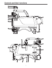
Lens connector [LENS]
The lens cable is connected to this connector.
Front MIC1 connector [MIC1]
A microphone (optional accessory) is connected here.
The power supply for the microphone can be connected
from this connector. What kind power is to be supplied is
set using the MIC1 power selector switch.
VF connector [VF]
The 2˝ viewfinder cable is connected to this connector.
Rear VF connector
This D-sub connector is used for Viewfinder interface.
Back light switch [LIGHT]
This light switch is used to make it easier to read the
characters on the camera’s back panel.
The brightness can be adjusted using the camera menu.
MIC1 Talk LED [TALK]
This LED lights up green when the INCOM1 MIC is
operational.
It blinks when the MIC has been forcibly set to OFF by a
remote control operation.
MIC2 Talk LED [TALK]
This LED lights up green when the INCOM2 MIC is
operational.
It blinks when the MIC has been forcibly set to OFF by a
remote control operation.
MIC2 selector switch [LINE/MIC]
This switch is used to select LINE or MIC for the input
signals.
Buildup unit I/F
This signal interface connector is used to connect the
Buildup unit.