


9
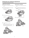
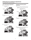
Controls and their functions
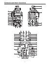
Back tally LED selector switch
This is used to set the back tally LED to ON or OFF.
Back tally LED
This lights when the tally signal is supplied.
This lights up red when the R tally signal is supplied,
green when the G tally signal is supplied, and red when
both the R and G tally signals are supplied.
RET switching control connector [RET CONT]
The cable of the RET switching box (optional accessory)
is connected here for controlling the ON/OFF settings of
RET1,
2, 3 and INCOM1, 2 MIC.
External I/O [EXT I/O]
This is the signal connector for interfacing with an
external device.
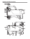
Camera HD-SDI output1 connector (BNC)
[HD-SDI1]
The camera HD-SDI images are output from this
connector.
Camera HD-SDI output2 connector (BNC)
[HD-SDI2]
Camera images, VF images or RET images can be
selected on the camera menu to output HD-SDI signals
from this connector.
Optional video connector (BNC) [AUX]
This is an auxiliary input/output connector.
Analog Y input or Prompt2 output signals can be
selected. When a down-converter (optional accessory)
has been installed in the camera, this connector can be
used as a VBS or D1 output connector.
Genlock sync input/PROMPT output connector
[PROMPT/GL]
When the GL/PROMPT selector switch is set to GL, the
reference signal (tri-level SYNC or B.B.) which is used to
genlock the camera is input to this connector; Genlock
sync signals are input to this connector when the CCU
is not connected. When it is set to Prompt1, the images
input from the CCU are output from this connector.
GL/PROMPT selector switch
This is used to select the genlock input or the input/output
(genlock input and PROMPT output) signals of the
PROMPT output connector.
ROP connector [REMOTE]
The remote operation panel (ROP, optional accessory) is
connected to this connector.
External power supply input connector [DC IN]
The input of the external DC power supply is connected
to this connector. (DC 10.8 V to 17 V)
MIC1 selector switch [LINE/FRONT MIC/MIC]
This is used to switch the input signal to LINE, FRONT
MIC or rear MIC.
Rear MIC1 connector [MIC1]
An audio component or microphone is connected to this
connector.
Rear MIC2 connector [MIC2]
An audio component or microphone is connected to this
connector.
Tally/DC output connector [TALLY/DC OUT]
The R or G tally signal is output from this connector
(open collector). A DC 12 V power supply (up to 1.0 A)
can also be supplied.
If the current exceeds the rating, the overcurrent
protection function is activated and the power is turned
off forcibly.
Earphone jack [EARPHONE]
When an earphone (optional accessory) is connected to
this jack, the INCOM1 receive signal and MIC1 monitor
signal can be heard.
Data trunk connector [TRUNK]
The trunk data [RS-422 2 or RS-232C 2] of the CCU
is input to and output from this connector.
MIC1 power selector switch
This is used to select what kind of power is to be supplied
to MIC1. (The switch is set to phantom 48 V, AB 12 V or
OFF.)
MIC2 power selector switch
This is used to select what kind of power is to be supplied
to MIC2. (The switch is set to phantom 48 V, AB 12 V or
OFF.)
Grip PTT switch [PTT]
This selector switch is used to set the INCOM1 MIC to
ON or OFF.
Grip RET switch [RET]
This is used as return image selector switch.
Optical filter selector switch [FILTER LOCAL]
This is pressed to adjust the optical filter manually.
When it is pressed again, the optical filter can be
controlled by the ROP.
Filter local LED [LOCAL]
This LED lights when the optical filter can be adjusted
manually.