


18
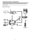
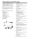
Outline of peripheral components
1 Camera control unit (CCU: AK-HCU931P)
This is the multi-format camera’s camera control unit. It
is connected to the multi-format camera using an optical
fiber cable (optional accessory).
As a standard feature, it supports SD video input and
output, and it can also support HD video input and
output by connecting the HD output unit (AK-HHD931P).
2 Remote operation panel (ROP: AK-HRP931P)
The ROP is connected to the CCU using the ROP cable
(optional accessory), and enables the camera, CCU and
lens to be operated by remote control.
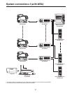
3 Master setup unit (MSU: AK-MSU930P)
When a multiple number of cameras and CCUs are
used, the MSU can operate up to 15 units either
separately or simultaneously by remote control. It can be
operated together with the ROP.
4 2 viewfinder (2VF: AJ-HVF20P)
This is the viewfinder for the multi-format camera.
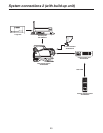
5 Build-up unit (AK-HBU931P)
This is an adapter used to mount a larger lens (optional
accessory) on the multi-format camera. Thereby, it
affords the same level of operability as that provided by a
larger camera.
6 LCD viewfinder (LCD VF: AK-HVF931P)
This is the LCD viewfinder for the multi-format camera. It
can be used at the same time as the 2 viewfinder. It can
still be operated when the system is built up.
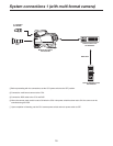
Component connections in an SD system
1 Component connections
Refer to pages 19 to 21 for the component connections.
After all the components have been connected (the
monitor system may be connected afterward), set the
CCU’s main power switch to the ON position. Then turn
on the camera’s power switch.
Component system configuration