


9
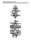
RCB connector [RCB]
The simplified remote control unit (RCB, optional
accessory) is connected to this connector.
External power supply input connector [DC IN]
The input of the external DC power supply is connected
to this connector. (DC 12V)
MIC1 selector switch [MIC1 F/R]
This is used to switch the MIC1 input signal to the front
or rear.
Rear MIC1 connector [MIC1]
An audio component or microphone is connected to this
connector.
Rear MIC2 connector [MIC2]
An audio component or microphone is connected to this
connector.
Tally output connector [TALLY OUT]
The R or G tally signal is output from this connector
(open collector). A DC 12 V voltage (approx. 1.0 A) can
also supplied.
Earphone jack [EARPHONE]
When an earphone (optional accessory) is connected to
this jack, the INCOM1 receive signal and MIC1 monitor
signal can be heard.
Data trunk connector [TRUNK]
The trunk data [RS-422 2] of the CCU is input to and
output from this connector.
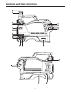
MIC1 power selector switch
This is used to select what kind of power is to be supplied
to MIC1. (The switch is set to phantom 48 V, AB 12 V or
OFF.)
MIC2 power selector switch
This is used to select what kind of power is to be supplied
to MIC2. (The switch is set to phantom 48 V, AB 12 V or
OFF.)
MIC1 Input gain selector switch
This is used to set the MIC1 input gain (in 10 dBm
increments from –20 to 60 dBm).
MIC2 input gain selector switch
This is used to set the MIC2 input gain (in 10 dBm
increments from –20 to 60 dBm).
RET selector switch [RET]
This is used as return image selector switch.
Optical filter selector switch [FILTER LOCAL]
This is pressed to adjust the optical filter manually.
When it is pressed again, the optical filter can be
controlled by the ROP.
Monitor output selector switch [MONI SEL]
This is used to select the images (Y/C, NAM, R, G, B)
which are to be output from the monitor output connector.
ND filter selector knob
This is used to adjust the optical filter manually when
LOCAL has been selected as the filter setting.
1: CAP, 2: Through, 3: 1/4, 4: 1/16, 5: 1/64
CC filter selector knob
This is used to adjust the optical filter manually when
LOCAL has been selected as the filter setting.
A: 3200K, B: 4300K, C: 6300K, D: Cross, E: DFO
Power save switch [CAM/VTR]
This is used to select the power supply status when VTR
recording has been temporarily stopped. It is not effective
when the CCU is connected to the camera.
Gain selector switch [GAIN]
This is used to select the gain for the camera images. It is
not effective when the CCU is connected to the camera.
Camera output selector switch [OUTPUT]
This is used to select the video output (CAM, BAR or
TEST). It is not effective when the CCU is connected to
the camera.
White balance selector switch [W.BAL]
This is set when there is no time to perform the coarse
adjustment of the white balance. It is not effective when
the CCU is connected to the camera.
PTT switch [PTT]
This selector switch is used to set the INCOM1 MIC to
ON or OFF.
Assignable switch [USER SEL]
Using the setting menu, user settings can be assigned
to this switch. When the switch is pressed, the assigned
user setting mode is established; when it is pressed
again, the selected mode is released.
SD card connector [SD CARD]
The setup card (optional accessory) is inserted here. For
details on its operation, refer to the menu.
Menu switch [MENU]
When this switch is pressed, the camera’s user menu is
output; when it is pressed again, the menu screen display
is cleared.
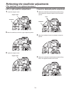
Controls and their functions