


11
INSTALLATIONS AND CONNECTIONS
WARNING
The installation described in these figures should be made
by qualified service personnel or trained system installers.
Cautions:
• This system must be installed within the protected
promise in accordance with the National Electrical
Code (NFPA70), and the local authorities having juris-
diction.
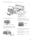
• Attach this unit to a flat wall with the supplied mounting
bracket. After the installation, secure the unit to prevent
dropping.
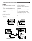
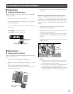
■ Caution on Installation
Secure the unit with the supplied mounting bracket to pre-
vent vibration, dropping and injury.
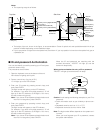
Notes:
• Keep the unit:
•
in the temperature between 0 °C and 40°C {between
32 °F and 104°F} and the humidity between 30 % and 80 %.
430 mm {17 in.}
211 mm {18 in.}
1 380 mm {54 in.} or more
(recommended)
80 mm {3 in.}
Top View Side View
400 mm {16 in.}
900 mm {35 in.}
1 300 mm {51 in.}
400 mm {16 in.}
900 mm {35 in.}
400 mm {16 in.} 400 mm {16 in.}
700 mm {28 in.} 700 mm {28 in.}
Floor
1 300 mm {51 in.}
Keep this area free
from obstructions
Keep this area free
from obstructions
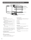
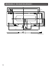
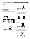
Coaxial cable (BNC)
Coaxial cable (BNC)
Camera power cable
General-purpose
power supply *
(24 V DC)
BM-ET500
(For recognition)
Camera 1
Camera 2
System Instruction (Maximum System)
OK
NG
BM-ET500
(For recognition)
In the case of Wiegand / RS-485 use
OK
NG
OK
NG
(For
enrollment)
Administration PC*
LAN
Electric lock*
Electric lock*
Door control box* Access server*
Camera 3
BM-ET500
BM-ED500
POWER ALARM
S3S2S1
Wiegand
or RS-485
* The use of the Administration PC was not evaluated by UL.
* The use of electric lock was not evaluated by UL.
* The use of door control box was not evaluated by UL.
* General-purpose power supply must be a UL Listed access control power limited device.
• Keep the unit away from:
•
direct sunlight or light reflection.
•
incandescent or halogen lighting.
•
places where shadow appear over the front panel.
•
noise. (for example, places near air conditioners or ven-
tilators)
•
electricity.
•
outdoor places.
•
vibration. (It may cause invalid recognition or injury.)
• Do not place anything inside the space described in
the illustration.
• This unit is for indoor use only.
• This unit must be mounted horizontally on the wall.
• Determine the optimum mounting height. The recom-
mendation is between 1.38 m {54 in.} and 1.5 m {60 in.}
for enrollment/recognition effectiveness.
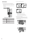
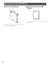
• Mount the bracket on the wall. Be sure to provide
access for video control and DC power from the control
unit.