


@2 SDI output connector [SDI]
(* only for GP-US932CUS, GP-US932CUSE)
This connector provides HD-SDI or SD-SDI output sig-
nals.
Important:
• Please use a high quality cable compatible with
HD-SDI.
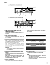
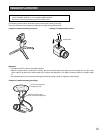
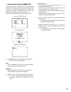
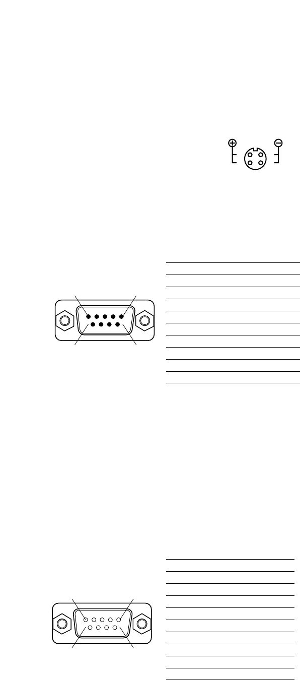
!8 12 V DC power connector [DC 12V IN]
This connector is used to connect an external DC
power supply of 12 volts (2 A or more).
Important:
• A class 2 power supply of 12 V DC (10.8 to 13.2
volts) shall be used.
Compatible connector
HR10A-7P-4S (73) manufac-
tured by HIROSE ELECTRIC
CO., LTD. (as of October 2007)
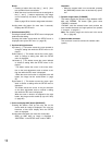
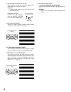
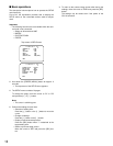
!9 RS-232C port [RS-232C]
This port is used to perform external control. Please
contact your dealer for further information.
12
5 1
9 6
1 5
6 9
1
2
4
3
Pin arrangement of
applicable connector
(Cable side)
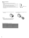
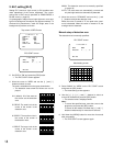
Pin number Output signal
1 GND
2 GND
3 R, Pr
4 G, Y
5 B, Pb
6 VIDEO
7 SYNC
8 GND
9 GND
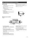
@0 S-video output connector [S-VIDEO]
This connector provides the luminance signal (Y) output
and color signal (C) output with synchronizing signals.
@1 RGB/YPbPr connector [RGB/YPbPr]
This connector provides the RGB signal (red, green,
and blue) output or the YPbPr signal (luminance, color
difference B, and color difference R) output. The output
signal can be set up with use of "OUTPUT SEL" in the
SETUP menu. (☞ page 19)
Pin number Signal
1 GND
2 TXD
3 RXD
4 DSR
5 GND
6 DTR
7 CTS
8 RTS
9 GND
(D-sub 9-pin connector,
male)
(D-sub 9-pin connector,
female)