


6 7
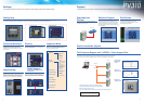
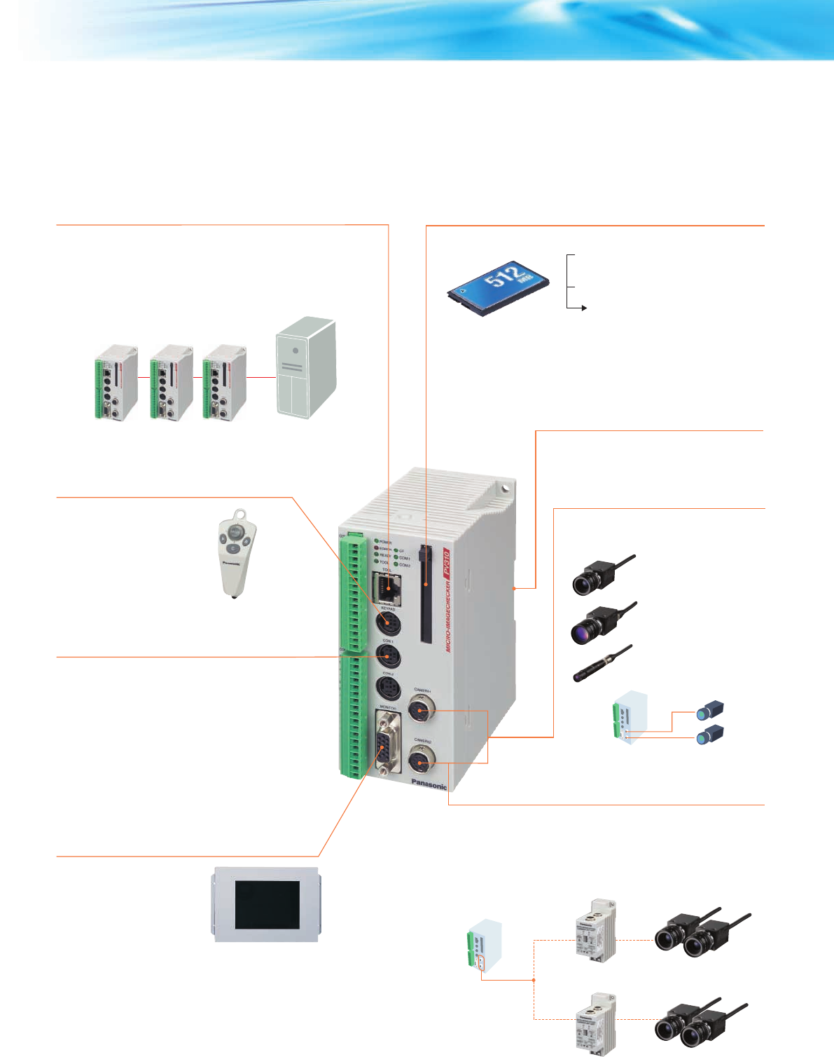
Full Selection of Interfaces
External interfaces are essential for image processing
devices of the future. The PV310 is equipped with a full
selection of interfaces that rival even large-scale devices.
PV310
PV310
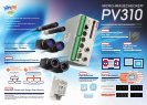
Two cameras
Operation Keypad
•
In RUN mode:
•
In the setting mode:
• Backs up setting data and image data
captured by the unit.
The dedicated keypad with an
ergonomic structure provides
excellent operability.
Up to two identical cameras can be
connected. The following camera types
are available.
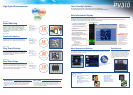
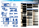
Functions
The numerical output function has been greatly
simplified so that even a novice can set it easily.
Operation has also become even easier as both
numerical calculations and judgment output can now
be set on the same screen (up to 96 formulas).
Upgraded
Detection of sub-pixel position possible with gray
scale matching. In addition, using the gray scale
differential processing function, shape inspection,
etc. can also be carried out simultaneously. Memory
capacity has been increased 4 times over previous
models, allowing support for an even wider range of
applications.
Based on the position information obtained by the
matching function, the registered object and detected
object are overlapped and compared on a pixel-by-
pixel basis. Any pixels with a difference in brightness
over a certain level are detected. The area value of
such pixels can then be used to make pass/fail
judgments.
Feature Extraction
Features, such as the number of objects, workpieces,
area, central coordinates, angle of the main axis,
projection width or perimeter length can be extracted.
Gray Scale Window
An inspection area can be created in a 256 gray
scale image, with a rectangular, circular or polygonal
shape, over the area where object detection is to take
place. An average value for the brightness data (gray
scale value) for all pixels in that area can be
calculated.
360° Contour Matching
Stable position detection is possible even for objects
that overlap because their contours can be extricated.
The range of settings has been doubled and support
has been added for 4 cameras.
Supported Models:
• Matsushita Electric Works PLCs
• OMRON Corporation - C, CV and CS1 series
• Mitsubishi Electric Corporation - A, Q and FX series
• Rockwell Automation DF1 protocol
• Fuji Electric SX series
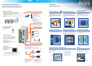
Ethernet Connection
• The PV310 can be connected to a LAN using high-speed Ethernet
(100BASE-TX) to meet various application requirements.
• Captured images and measurement data can be transmitted to a PC at
high speed even during operation.
• The inspection status of multiple PV310 units can be monitored from a
single PC.
• With the high-speed connection to a PC, backing up image data is also
easy.
PC
External Memory (CF Card) Support
Note: Backup image data can be used as
regular bitmap files on a PC.
DIN Rail Installation
Connection of up to Two
Identical Cameras
Connection of up to Four Cameras
by a Camera Switching Unit
• Can save captured images.
[Storage capacity:
Approx. 2,000 images (512 MB)]
• Saves inspection results.
Facilitates trend tracking and data
analyses.
Cameras
PV310
Inspection programs for as many
as 64 product types can be set.
Smart Matching
Improved
Differential Function
Numerical Calculation/
Judgment Output
NG
Detects registered
template
Detection Image
Template
Matching
detection
Difference detected =
Previous
The shape of the inspection area can be set to
match particular targets. Mask area settings
can also be combined to allow efficient
inspections to be carried out only on the
necessary parts.
Mask
Rotation/Position Adjustment
Mask
Multiple Adjustment
Highly accurate and reliable inspection is realized by automatically adjusting object orientation
and stop position deviation.
Complicated adjustments are also possible using the multiple adjustment function.
Search area Inspection object
Position
adjustment 1
Position
adjustment 2
Detection Image
Position Adjustment
Rotation Adjustment
Multiple Adjustment
Priority Adjustment
Inspection
area
Mask
PLC Link Function
• The PV310 can communicate easily with external
devices, such as PLCs, using the RS232C port.
• The PV310 can be connected to other companies'
PLCs without requiring additional programming. Of
course it can be connected to our PLCs, too.
VGA Monitor
Judgment results and program
settings are displayed in color for
outstanding visibility.
(Captured images are in black
and white.)
Up to four identical standard or double-speed random cameras can be
connected using a camera switching unit (option: ANPV3700).
* Excluding Ultra-compact camera
This connection is ideal for:
• Control of different inspections by a single controller unit
• Inspection of wide areas, and positioning of workpieces during the LCD
lamination process, etc.
Note: Commercially available VGA monitors may also be connected
(devices supporting horizontal synchronous frequency: 31.466KHz
and vertical synchronous frequency: 59.94KHz only.)
Operation cannot be guaranteed with devices from other manufacturers.
Standard camera
[ANM832 (CE)]
Double-speed random
camera [ANM831]
Ultra-compact camera
[ANPVCA1012]
Camera switching unit
(ANPV3700)
•
Camera Switching Mode
Images taken by either of two cameras
connected to the camera switching unit
are output to the PV310.
* Available for ANM832 (CE) and
ANM831
•
Camera Image Split Mode
(top/bottom split and left/right split)
Half images taken by two cameras are
combined into one, which is then
output to the PV310.
* Available for ANM832 (CE) only