


-29-
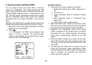
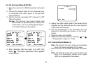
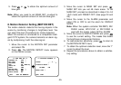
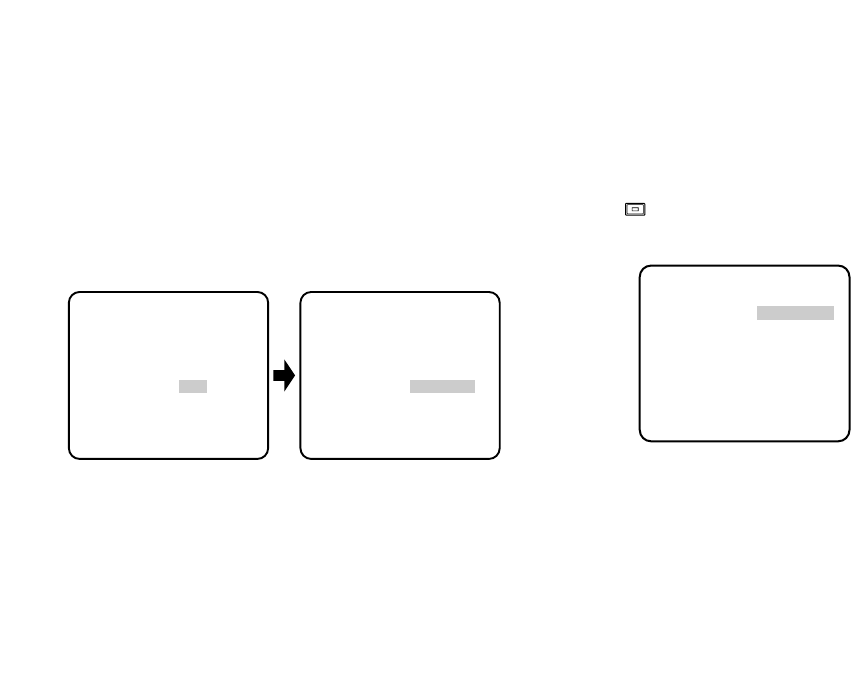
3. Confirm that the INT parameter changed to EXT
(VBS) on the menu.
Caution: The gen-lock input signal should meet
the EIA RS-170A specifications and should not
contain jitter, such as a VCR playback signal,
as it could disturb synchronization.
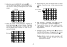
4. After confirming that the cursor is on EXT (VBS),
press . The phase adjustment menu appears
on the monitor.
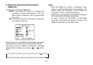
6. The VS gen-lock mode has a submenu for horizon-
tal phase adjustments. When the cable length of
the video output or the gen-lock input is changed,
the horizontal phase must be re-adjusted.
7. The line-lock mode has a submenu for line-lock
vertical phase adjustment. If the camera installation
is relocated, check the vertical phase adjustment
again since the AC line phase may be different.
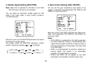
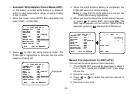
6-1. VBS Gen-lock Mode (EXT(VBS))
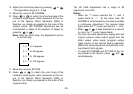
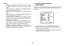
1. Move the cursor to the SYNC parameter and select
INT.
2. Connect the coaxial cable for the blackburst or
composite color video signal to the gen-lock input
connector.
5. Supply the video output signal of the camera to be
adjusted and the reference gen-lock input signal to
a dual-trace oscilloscope.
6. Set the oscilloscope to the horizontal rate and
expand the horizontal sync portion on the oscillo-
scope.
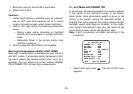
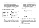
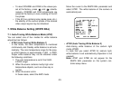
7. Move the cursor to H PHASE.
** SYNC **
H PHASE ........I
- +
SC COARSE 1(1--4)
SC FINE ....I....
- +
RET END
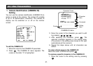
** CAM SET UP **
CAMERA ID OFF
ALC/ELC ALC
SHUTTER OFF
AGC ON (DNR-H)
SENS UP OFF
SYNC INT
WHITE BAL ATW1
MOTION DET OFF
LENS DRIVE DC
END SET UP ENABLE
↵↵
↵
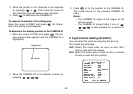
** CAM SET UP **
CAMERA ID OFF
ALC/ELC ALC
SHUTTER OFF
AGC ON (DNR-H)
SENS UP OFF
SYNC EXT(VBS)
WHITE BAL ATW1
MOTION DET OFF
LENS DRIVE DC
END SET UP ENABLE
↵↵
↵