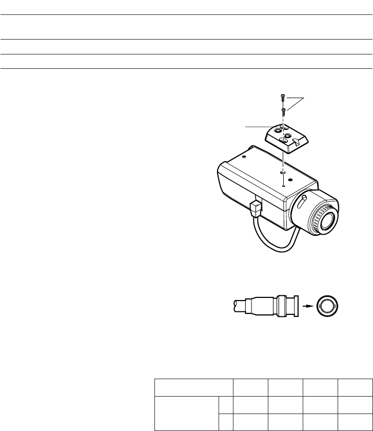
v Connect a coaxial cable (optional) to the
video output connector.
Connect the video output connector to the monitor or other system device with the procured
coaxial cable. The maximum extensible length is shown in the table.
12
Camera mounting
screws
Mount adapter
Screw hole
(1/4-20 UNC)
VIDEO OUT
• When attaching the mount adapter
removed from the top of the camera onto
the bottom of the camera, do not use
screws other than the removed ones.
Otherwise, it may cause a malfunction or
the camera may fall off.
Recommended tightening torque:
0.39 N·m {4 kgf·cm}
Type of coaxial cable
Recommended
maximum
cable length
RG-59/U
(3C-2V)
250
825
RG-6/U
(5C-2V)
500
1 650
RG-11/U
(7C-2V)
600
1 980
RG-15/U
(10C-2V)
800
2 640
(m)
(ft)
Mounting place
Ceiling
Model
WV-7010A
Recommended
screw
M8
Number of
screws
3 pcs.
Minimum pull-
out strength
196 N {20 kgf}
Wall WV-831 M8 4 pcs.
921 N {94 kgf}
The mounting requirements are shown as follows.
b Connect the power cord between the camera and the power source.
Important:
• Clamp the coaxial cable and power cable along the camera mount bracket to prevent
tangles of the cable.
• 120 V AC 60Hz (WV-CP280)
Connect the power cord to an electrical outlet of 120 V AC 60 Hz.


