


14 Pelco Manual C1488M-A (9/98)
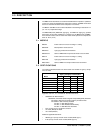
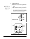
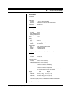
From controller To 4-Wire terminal on circuit board
RX- TX-
RX+ TX+
TX- RX-
TX+ RX+
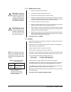
NOTE:
Connect only a low volt-
age device to the relay output.
Maximum current rating of the re-
lay contacts is two amperes.
CAUTION:
The maxi-
mum output of AUX 2 is
150 mA. If you connect a
device that draws more
current, you could destroy
the output transistor. The
output is intended to drive
logic circuits or low-current
devices. If higher current
is required, connect the
output to a relay.
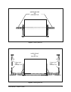
CAUTION:
Leave ad-
equate slack in the wiring
to permit the door to open
without pulling on the con-
nectors.
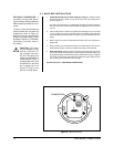
4. Control - If you are using a Coaxitron
®
controller, control signals will be trans-
mitted over the video coax.
If you are using RS-422 (P or D) control signals, connect the control lines from
the controller to the circuit board. Connect the wires as follows:
5. Heater/Fan - The heater/fan is not used on indoor models.
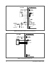
6. Alarm Inputs - (Spectra™ [Version 3.0] and Spectra II™ Only) If you need
alarm inputs, connect them. The maximum number of alarm inputs is seven.
Refer to Figure 6 for a typical wiring example. Alarm inputs require a ground
signal through a contact closure, such as a switch.
7. AUX 1 - (Spectra™ [Version 3.0] and Spectra II™ Only) An AUX 1 com-
mand from the controller will activate the relay output. If you need the relay, wire
it as required. Refer to Figure 6. The relay contacts are shown when AUX 1 is
inactive. When an AUX 1 command is issued, the relay contacts will reverse and
remain latched until a clear command is issued.
8. AUX 2 - (Spectra™ [Version 3.0] and Spectra II™ Only) An AUX 2 command
from the controller will place a ground at the output of AUX 2 to operate the device
connected to it. The output will remain latched until a clear command is issued. If
you need the AUX 2 output, wire it as required. Refer to Figure 6 for typical wiring
examples. The AUX 2 output is an open collector transistor driver which is capable
of passing a maximum of 150 mA at 32 VDC. It is capable of driving TTL logic
circuits or low-current reed relays. If you use an external relay, make sure that both
the supply voltage and the current requirements are well below the maximum of
32 VDC and 150 mA. Exceeding these values will cause permanent damage to
the dome. If you are not familiar with open collector drive requirements, contact
Pelco technical support for assistance.
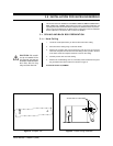
9. Close the door and tighten the thumbscrew securely.
10. Turn on power to the back box. The red LED on the interconnect door should
light. The fan will not operate until a dome drive is installed.
If the LED does not light, correct the trouble before proceeding. Refer to Sec-
tion 5.0, TROUBLESHOOTING.
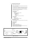
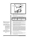
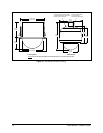
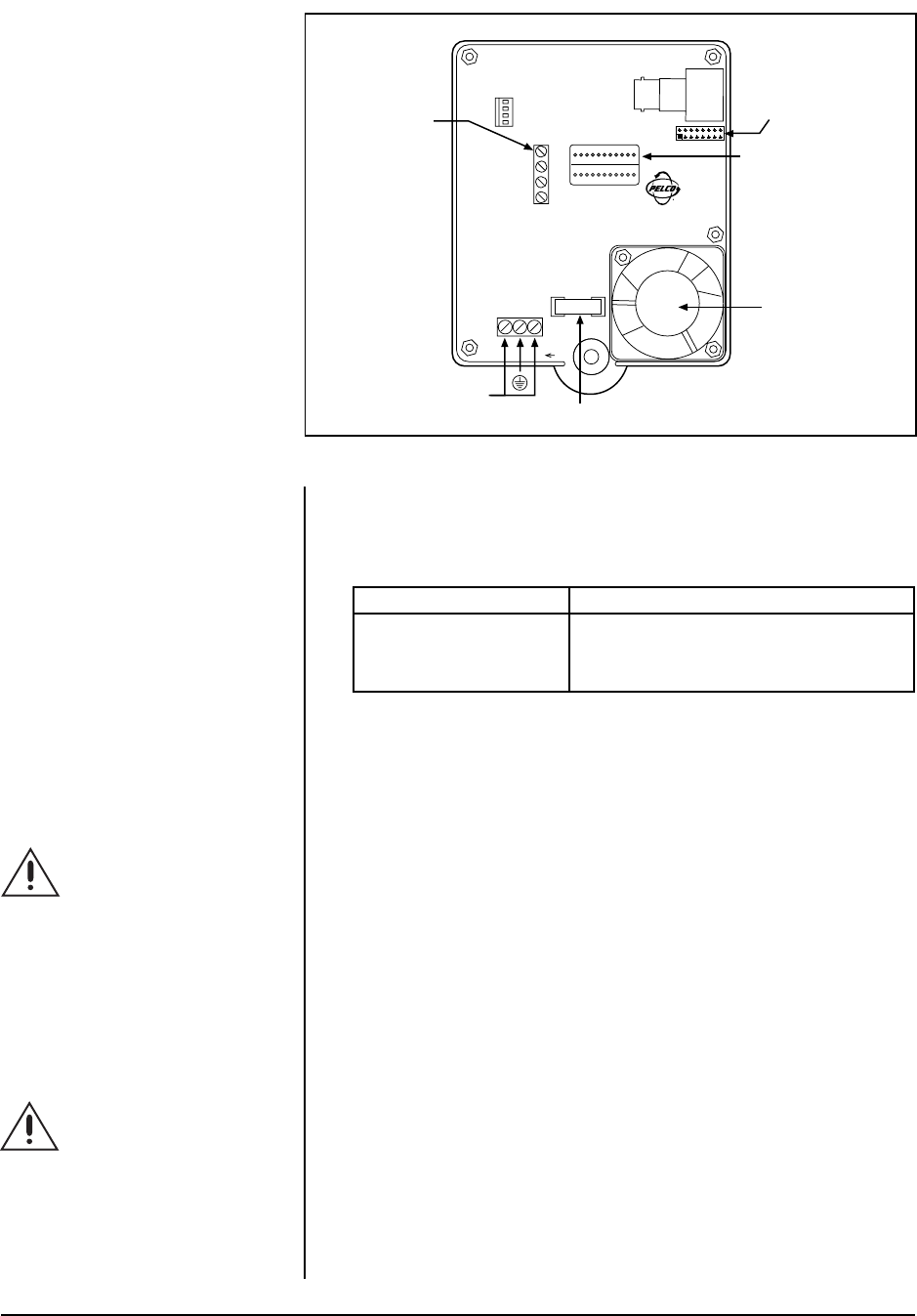
HTR/FAN
RX–
RX+
TX–
TX+
PWR IN
FUSE
1.6 A
DOME DRIVE
CONNECTOR
RS-422
CONTROL
SIGNALS
POWER
(24 VAC ONLY)
FAN
24 VAC
MIDDLE
PIN IS
GND
VIDEO
CONNECTOR
FOR OPTIONAL
TRANSLATOR
SUBASSEMBLY
Figure 11. Interconnect Circuit Board for Spectra™ Lite