


8 Pelco Manual C1488M-A (9/98)
3.1.2 Suspended Ceiling
1. Remove the ceiling tile from the ceiling.
2. Locate the center point to drill a hole in the tile.
3. Drill a hole in the ceiling tile using a 3/32-inch drill bit.
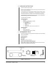
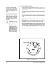
4. Remove the compass tool from the parts bag (refer to Figure 2). Press the
stud of the compass tool into the hole in the ceiling. Insert a pencil in the hole
in the other end of the compass and mark a circle on the ceiling.
5. Carefully cut the circle out of the ceiling tile.
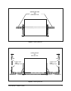
6. Remove the conduit fitting, lock nut, and safety chain bracket from the parts
bag and attach them to the back box as shown in Figure 3.
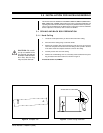
7. Refer to Figure 4. Compress the spring clips on the back box with your hands
and push the back box through the hole in the ceiling tile. The spring clips will
spring out when they clear the ceiling tile.
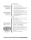
8. Refer to Figure 5. Tighten the screws until the spring clips hold the back box
firmly to the ceiling tile. You will hear a clicking noise when the screws are tight.
Do not install the ceiling tile in the ceiling yet.
Proceed to Section 3.2, WIRING.
3.2 WIRING
Bring wiring to the back box opening in the ceiling. Do not attach the wiring to the
back box. You will do that later.
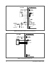
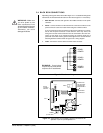
Refer to Figure 6 for the wiring diagram for Spectra™ (Version 3.0) and Spectra II™,
and to Figure 7 for the Spectra™ Lite.
Wiring is required for power, earth ground, and video.
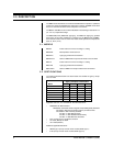
Refer to Table A for the type of video coaxial cable to use.
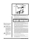
Input power is 24 VAC only. Power consumption is 25 vA per dome for indoor models
and 90 vA for outdoor models. Refer to Table B to determine the size of wire to use.
Use a 24 VAC transformer with the following minimum vA:
30 vA per dome For indoor models (without heater)
100 vA per dome For outdoor models (with heater)
Refer to Figure 9 for wiring multiple domes from the same transformer.
If you will use a Coaxitron
®
controller, the control signals to operate the dome drive
will be transmitted over the video coax. The RS-422 control lines are not used.
If you will not use a Coaxitron
®
controller, use the RS-422 control lines. Use 22-
gauge wire. The distance will be the same as the video coax.
Optional wiring may be provided for alarm inputs (maximum of seven), relay output,
and auxiliary output.
Proceed to Section 3.3, BACK BOX INSTALLATION.
CAUTION:
The ceiling
tile must be capable of
supporting 16 pounds
(7.3 kg) of weight. If the
ceiling tile will not support
this weight, use the op-
tional SD5-P metal panel.
CAUTION:
Be careful
not to cut outside of the
line. If you do, you may not
be able to install the back
box. Also, the trim ring
may not cover the hole.
NOTE:
The dome will stop oper-
ating if the voltage at the dome
drops below 18 VAC. It will turn
back on when the voltage exceeds
18 VAC.
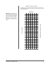
Cable Type* Maximum Distance
RG59/U 750 ft (229 m)
RG6/U 1,000 ft (305 m)
RG11/U 1,500 ft (457 m)
Table A. Video Coaxial Cable
Wiring Distances
* Minimum cable requirements:
75 ohms impedance
All-copper center conductor
All-copper braided shield with
95% braid coverage