


6 C1448M-F (9/08)
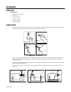
SUSPENDED CEILING
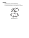
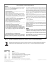
1. Remove the ceiling tile from the ceiling. Insert the compass tool (supplied) into the center of the tile. (If necessary, use a 3/32-inch bit to
drill a hole.) Draw a circle on the tile using the compass tool and a pencil. Carefully cut out the circle.
NOTE: The ceiling tile cannot be thinner than 0.50-inches (1.27 cm) or thicker than 1.75 inches (4.45 cm).
P
Figure 3. Preparing the Ceiling Tile
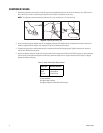
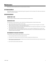
2. Attach a conduit fitting (not supplied), lock nut (not supplied), and safety chain bracket. Attach to the bracket one end of a safety chain/
cable (not supplied) that will support up to 16 pounds (7.3 kg). Do not attach the other end yet.
3. Compress the spring clips on the back box and push it through the hole until the clips spring back. Tighten the screws until you hear a
clicking noise. Reinstall the ceiling tile.
4. Remove an adjacent ceiling tile. Prepare the wiring for camera and lens power; refer to Table A and Table B on page 7 for wiring distances.
Pull the wiring into the back box through the conduit fitting. Attach the safety chain to a support structure (refer to Figure 2 on page 5).
Replace the adjacent ceiling tile.
*Minimum cable requirements:
75-ohm impedance
All-copper center conductor
All-copper braided shield with 95% braid coverage
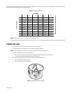
Table A. Video Coaxial Cable Requirements
Cable Type* Maximum Distance
RG59/U
RG6/U
RG11/U
750 ft (229 m)
1,000 ft (305 m)
1,500 ft (457 m)