C1448M-F (9/08) 7
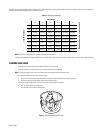
Table B shows the recommended maximum distances for 24 VAC applications and are calculated with a 10 percent voltage drop. (Ten percent is generally
the maximum allowable voltage drop for AC-powered devices.)
NOTE: Distances are calculated in feet; values in parentheses are meters.
For example, an enclosure that requires 80 VA and is installed 35 ft (10 m) from the transformer would require a minimum wire gauge of 20 AWG.
CAMERA AND LENS
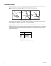
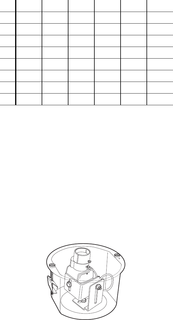
1. Extend the lens to the maximum length before installing it in the back box.
2. Attach the camera to the tilt table with the 1/4-20 screw and washers (supplied).
NOTE: The torque applied to the camera mounting bracket nut should not exceed 40 pound-inches.
3. To ensure that the lens will not touch the lower dome:
• Place the lower dome over the back box with the camera and lens installed (do not attach the dome).
• If the lens touches the lower dome, adjust the tilt table assembly.
4. Refer to the manual supplied with the camera and lens for the following information:
• How to connect power and video wiring
• How to make camera and lens adjustments
Figure 4. Installing the Camera and Lens
Table B. VAC Wiring Distances
Wire Gauge
Total VA consumed
20 18 16 14 12 10
Maximum distance from transformer to load
10 283 (86) 451 (137) 716 (218) 1142 (348) 1811 (551) 2880 (877)
20 141 (42) 225 (68) 358 (109) 571 (174) 905 (275) 1440 (438)
30 94 (28) 150 (45) 238 (72) 380 (115) 603 (183) 960 (292)
40 70 (21) 112 (34) 179 (54) 285 (86) 452 (137) 720 (219)
50 56 (17) 90 (27) 143 (43) 228 (69) 362 (110) 576 (175)
60 47 (14) 75 (22) 119 (36) 190 (57) 301 (91) 480 (146)
70 40 (12) 64 (19) 102 (31) 163 (49) 258 (78) 411 (125)
80 35 (10) 56 (17) 89 (27) 142 (43) 226 (68) 360 (109)


