


Pelco Manual C538M-A (3/04) 19
5.0 OPERATION
5.1 OPERATIONAL OVERVIEW
The basic function of the REL unit is to allow the user/operator to control various
peripheral equipment via relay contacts. Each REL unit processes and executes
only commands with addresses that match that of the RELs (frame address). When
an REL receives a command with an inappropriate address, it passes it on to the
next unit (if applicable) via its OUT port.
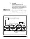
When power is first applied to the unit, RAM is cleared and initialization routines
are called. The power LED is lit, operational chips are configured, interrupt priori-
ties are set and the Data LED starts flashing on and off at about 1/2 second
intervals (refer to Section 3.1.2, LEDs). The unit is waiting for its first valid com-
mand.
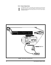
5.2 OPERATING THE CM9760-REL FROM THE CM9760-KBD
Direct control operation of peripherals attached to RELs from a CM9760-KBD is
relatively straightforward once you have determined which GPI to call and AUX to
activate. In the next section, we discuss two methods for obtaining this information.
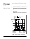
Method 1 uses Figure 16 and Table A; Method II uses the CM9760-REL GPI/AUX
CALCULATOR only (ignore VCRC references on the backside of the calculator).
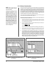
5.2.1 Information Retrieval
OUR EXAMPLE: Assume you have five cascaded REL units and you wish to acti-
vate the peripheral device attached to relay 39 on REL unit 5.
What information do you need to know?
Where can you find the information?
First, you need to determine two things:
1. Which GPI to call of the 704 available.
2. Which AUX, associated with the GPI, to press.
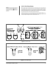
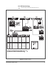
Method I – Table A and Figure 15
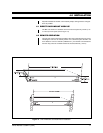
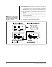
Figure 15 is a physical representation of OUR EXAMPLE. We will also use it to
recap the information needed to perform the steps illustrated in Figure 16.
First, the GPI range. Every REL unit is associated with a range of eight GPIs. In our
sequential run of cascaded units, REL 5 has a GPI range of 33-40. (Had we instead
been interested in REL unit 1, then the GPI range we would want would be 1-8).
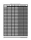
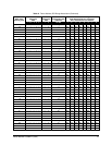
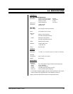
The GPI range can be determined in a number of ways: (1) you may already have a
list or (2), you can match the frame/sub-frame address on the physical REL unit
with those listed in Table A and thus find the GPI range and (3), if you already know
the frame/sub-frame address, you can use Table A alone.
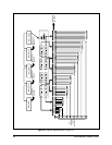
Starting on the left in Figure 15, you can follow the line to the right of GPI 37 over to
where it intersects with the AUX associated with relay grouping 33-40. GPI 37,
therefore, is the specific GPI we need to accomplish our task. Of eight AUX associ-
ated with GPI 37, we can see that AUX 7 is the one we need. Follow the vertical line
from AUX 7 up to where it intersects the associated relay numbers and you will find
number 39.