


2 Pelco Manual C538M-A (3/04)
CONTENTS
Section Page
1.0 GENERAL................................................................................................... 3
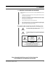
1.1 IMPORTANT SAFEGUARDS AND WARNINGS ................................ 3
2.0 DESCRIPTION ........................................................................................... 4
2.1 MODELS ............................................................................................ 4
3.0 PRE-INSTALLATION INFORMATION......................................................... 5
3.1 FRONT VIEW AND DIP SWITCH ACCESS....................................... 5
3.1.1 DIP Switches .......................................................................... 5
3.1.2 LEDs....................................................................................... 5
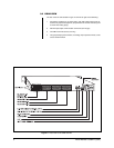
3.2 REAR VIEW........................................................................................ 6
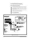
3.2.1 REL Contact Pair Connections............................................... 7
3.2.2 External Relay Wiring Considerations .................................... 8
3.2.3 Communication Connectors ................................................... 8
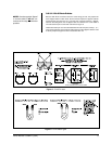
3.2.3.1 DB-9 Connector ..................................................... 8
3.2.3.2 RJ-45 Data Cables................................................. 9
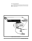
3.2.4 Power Connections ............................................................... 10
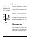
3.3 SETUP............................................................................................... 11
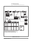
3.3.1 Preliminary Discussion.......................................................... 11
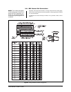
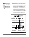
3.3.2 DIP Switch Settings............................................................... 13
3.3.3 Software Considerations ....................................................... 16
4.0 INSTALLATION .......................................................................................... 17
4.1 DIRECT RACK-MOUNT HOOK-UP .................................................. 17
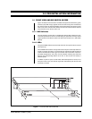
4.2 REMOTE OPERATION...................................................................... 17
4.3 DAISY-CHAINING.............................................................................. 18
5.0 OPERATION .............................................................................................. 19
5.1 OPERATIONAL OVERVIEW ............................................................. 19
5.2 OPERATING THE CM9760-REL FROM THE CM9760-KBD ............ 19
5.2.1 Information Retrieval ............................................................. 19
5.2.2 Keyboard Operation .............................................................. 21
6.0 SPECIFICATIONS ..................................................................................... 23
7.0 WARRANTY AND RETURN INFORMATION ............................................ 24
LIST OF ILLUSTRATIONS
Figure Page
1Front View with Panel Removal ............................................................ 5
2 Rear View of the CM9760-REL ............................................................ 6
3 Relay Interface Contact Configuration..................................................7
4 External Relay Wiring ........................................................................... 8
5 RJ-45 Pin-outs......................................................................................9
6 RJ-45 Cable Types ...............................................................................9
7Power Input Fuse Replacement ..........................................................10
8 Relationship of Frame Address Space and the Relay Interface Unit...11
9 Relationship of Frame Address Space with Respect to Starting
Address and the Relay Interface Units ................................................ 12
10 DIP Switch Functions .......................................................................... 13
11 Configuring the GPI Define File for REL Operation.............................16
12 Configuring the COMMS File for REL Operation ................................ 16
13 Unit Dimensions and Rack-Mount Installation.....................................17
14 Relay Unit Daisy-Chain Configuration .................................................18
15 Physical Representation of Figure 16 ...............................................20
16 Controlling REL Output Contacts From the CM9760-KBD ...............22
LIST OF TABLES
Table Page
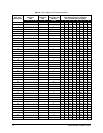
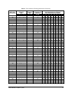
AFrame Address, GPI Range Association ..........................................14