20 C3401M-A (1/06)
Using the supplied RJ45-10 connector:
a. Connect the supplied RJ45-10 connector to your wiring and then plug the connector into the dome drive.
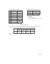
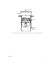
Refer to Figure 6, Table D, Table E, and Table F for wiring connections. Note that you can connect video using
either an unshielded twisted pair (UTP) of wires (refer to Table D) or coaxial cable (refer to Table E.) A BNC
connector for coaxial cable is attached to the dome drive.
If you are wiring more than one dome drive to the same transformer, connect one side of the transformer to pin
9 of the RJ45-10 connector on all modules. Connect the other side of the transformer to pin 10 of the RJ45-10
connector on all modules. Failure to connect all modules the same way will cause the cameras to be out of
phase with each other and may produce a vertical roll when switching between cameras.
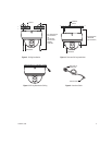
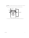
b. Turn the surface ring upside down, and place it on the inside of the ceiling tile. Refer to Figure 8.
c. Attach the dome drive to the ceiling tile and surface mount ring with the two #10 x 1.50-inch self-tapping
screws (supplied). Refer to Figure 8.
d. Replace the ceiling tile.
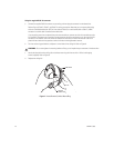
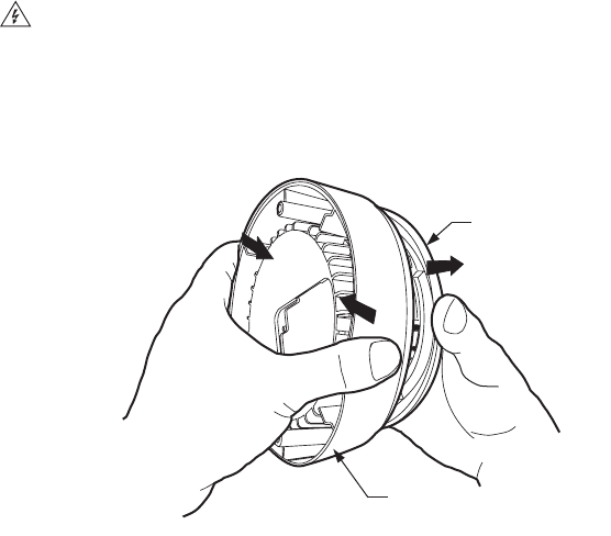
Figure 7.
How to Remove Surface Mount Ring
WARNING:
Do not over-tighten the mounting hardware. Doing so can impede the pan movement of the dome drive.
DOME DRIVE
SURFACE
MOUNT RING


