Pelco Manual C2913M-F (08/05) [ 11 ]
RJ45-10 Connections
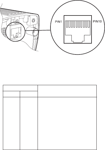
The RJ45-10 connector allows video (composite and twisted pair except MC3710S models) and power
connections to be made to the camera using a single Cat5-style cable.
NOTE: The PCM150 camera mount is designed for the MC3610 and MC3710 Series camera. It comes with
preconfigured auxiliary connectors and cables as well as an easy-to-wire adapter plate.
Before installation, identify the RJ45-10 connector leads to be used. To create the connection you will need a
Cat5 cable with the appropriate number of pairs and an 8-way or 10-way RJ45-10 connector. You will also need
a crimping tool capable of cutting, stripping, and crimping RJ50 (10P10C) connectors.
Wire the cable and connectors according to Table C. (More information about wiring each pair of leads appears
in the text below the table.) Then plug the auxiliary connector into the camera.
Figure 5. RJ45-10 Connector
Table C. RJ45-10 Pinouts
* MC3610H-6, MC3610H-6X, MC3710S-6, MC3710S-6X, MC3710H-6 and MC3710H-6X models only
† All models except MC3710S
Composite Video Out
Pins 2 and 3 provide a composite video output signal.
NOTE: The RJ45-10 composite video out is only intended to be used to route the video signal to a break-out
box where a conventional coaxial connection will be made.
The following instructions apply to 10-way connectors. When using an 8-way connector, refer to table C.
8-WAY 10-WAY
- 1 No connection
1 2 Composite video ground
2 3 Composite video
3 4 No connection
4 5 Twisted pair video output (-) †
5 6 Twisted pair video output (+) †
6 7 No connection
7 8 24 VAC *; 12 VDC (-)*
8 9 24 VAC *; 12 VDC (+)*
- 10 No connection
PINS
FUNCTION


