


PELCO Manual C426M-F (2/98)
9
Part II
Pan/Tilt Assemblies
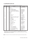
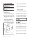
2–1.0 DESCRIPTION
The pan/tilt assembly is a “mini” light duty pan/tilt for
loads up to 15 lbs and is factory pre-wired for all con-
trol functions (pan and tilt, motorized zoom lens, cam-
era power (24 VAC), and video). All connections are
made at the input connector, eliminating the need for
wiring harnesses. This greatly reduces installation time,
while increasing reliability and serviceability.
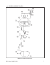
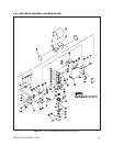
2–2.0 INSTALLATION
In order to insure proper wiring and system operation
of all components, it is highly recommended that the
pan/tilt and the associated control equipment be tested
in your facility before field installation is attempted.
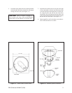
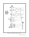
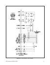
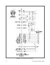
Wire the control cable in accordance with Figures 2-1
through 2-3.
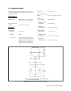
2-2.1 CONDUCTOR AND CABLE
REQUIREMENTS
Conductors
The following are the conductor requirements:
SB2800/SB2801/
SB2800-SL Pan/Tilt (5 plus ground),
Lens (4), Camera AC (2)
SB2800/PP Pan/Tilt (9 plus ground),
Lens (8), Camera AC (2)
SB2800-SL/PP Pan/Tilt (10 plus ground,
Lens (8), Camera AC (2)
Cable Distances – Hard Wire Controls
The following cables distances are for hard wire con-
trols:
Pan/Tilt Functions:
5 Conductors 6 Conductors*
20 Awg 110 ft (33.53 m) 210 ft (64.01 m)
18 Awg 180 ft (54.86 m) 330 ft (100.58 m)
16 Awg 290 ft (88.39 m) 530 ft (161.54 m)
*Using 2 conductor motor common
Lens Functions:
22 Awg 600 ft (182.88 m)
20 Awg 1,000 ft (304.80 m)
18 Awg 1,500 ft (457.20 m)
Camera Power
2 Conductors (24 VAC)
Consult the camera manufacturer or factory for trans-
former power distances.
Cable Distances – Coaxitron
The following cable distances are for Coaxitron con-
trols:
Up to a maximum of 750 feet on a single coax (RG59/
U) from the receiver to the transmitter.
NOTE: To extend the distance to 3,000 feet on
RG59/U coax, use the Pelco EA2000 Half Duplex
Equalizing Amplifier.
2–2.2 WIRING
Cable distances should not exceed the distances speci-
fied in Section 2-2.1, Conductor and Cable Require-
ments. The following are some recommended common
installation practices.
1. Always use jacketed stranded multi-conductor in-
terconnecting cable between the control and the
pan/tilt unit, with additional conductors than
needed for future servicing and or additions.
2. Always use color-coded conductors for ease of
wiring and to identify functions at a later date.
3. Keep a wiring diagram with the system for later
use and reference.
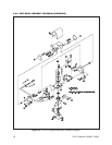
When the pan/tilt assembly is mounted in the inverted
position, the LEFT/RIGHT and UP/DOWN functions
are reversed during operation. To correct this problem,
reverse the LEFT/RIGHT functions in the control cable
(pins 3 and 7) at the pan/tilt or control and the UP/
DOWN functions (pins 5 and 6) at the pan/tilt or con-
trol.
NOTE: If you have purchased the C1906, C1906/
PP, C1925 or C1925/PP factory pre-wired cables,
correction for reversal of these functions has al-
ready been made in the cable. You do not need to
reverse the pins for inverted mounting if you use
the above mentioned cables with your pan/tilt.