


PELCO Manual C426M-F (2/98)2
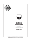
Part I – SB3-1/SB3-2 and
SB2800 Series Enclosures
PREFACE: There are two parts to this manual.
Part I covers the SB3-1, SB3-2, and SB2800 Se-
ries Dome Enclosures. Part II covers the
PT2801000 Series pan/tilt assemblies which are
used in the SB2800 Series Dome Enclosures.
Please refer to the applicable sections of this
manual when installing your system.
1–2.0 SCOPE
The information contained within this manual covers
the installation and operation of the SB3-1/SB3-2 and
SB2800 Series Discreet Surveillance Enclosures.
1–3.0 DESCRIPTION
The SB3-1/SB3-2 and SB2800 series are low profile
discreet enclosures designed for ease of installation, re-
location and service in standard 2' x 2' or 2' x 4' false
ceiling grids. Available with a black opaque or mirrored
lower dome, these domes combine concealed 355° sur-
veillance (360° on SL models) with distortion-free view-
ing. The lower dome effectively conceals the camera
while providing an inconspicuous viewing window with
a light attenuation factor of one (1) f-stop for the black
opaque dome and 2 f-stop light loss for the mirrored
dome. There is, of course, no light attenuation factor
for the SB2801 clear dome.
The dome and camera assembly rotate at a speed of 10
degrees/second on a balanced roller system for com-
plete 355°/360° surveillance coverage. The back box is
constructed of aluminum to meet fire code requirements
for installation in open plenum ceilings. The SB3-1/
SB3-2 and SB2800 will accept Pelco lenses up to 110
mm, increasing the flexibility of the system design and
application.
To simplify installation even further, Pelco offers sys-
tem packages with factory installed standard compo-
nents from its regular product line. This dramatically
reduces installation time and cost and assures the con-
tinued availability of replacement parts.
1–4.0 INSTALLATION
1–4.1 UNPACKING INSTRUCTIONS
Save the shipping carton and plastic packing, in case
the unit has to be returned for credit or repair.
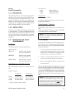
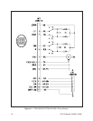
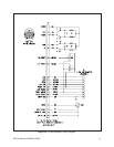
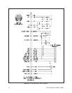
1–4.2 WIRING INSTRUCTIONS
SB2800 Series system packages include pan/tilt assem-
blies which are pre-wired for all control functions –
pan/tilt, motorized zoom lens, camera power (24VAC)
and video. All connections are made at the input con-
nector, eliminating the need for wiring harnesses made
in the field. Wire the control cable per Section 2-2.0,
Part 2 and the referenced diagrams, or use factory as-
sembled pretested cables C1906, C1906/PP, C1925, or
C9125/PP.
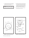
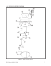
1–4.3 INSTALLATION INSTRUCTIONS
Your dome is supplied in two ways; as a passive dome
(SB3-1/SB3-2) for use as a dummy dome or with a fixed
camera (utilizing the CM3000 mount), or with a fac-
tory installed pan/tilt assembly (SB2800 series mod-
els). To install the dome or dome system, perform the
following steps (see Figure 1-2):
1. Handle the lower dome with care so as not to
scratch or get fingerprints on the viewing window.
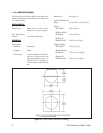
2. Mount the back box directly into a 2' x 2' false
ceiling grid and make certain that the assembly sits
flat on the grid.
NOTE: When installing the enclosure in a 2' x 4'
ceiling, cut the ceiling tile in half and install an
additional “T” rail for support. If further support is
required, install an eyebolt in the plywood base of
the back box and run a guy wire to secure the sur-
face.
3. Mount the camera/lens onto the optional fixed
mount (CM3000) or pan/tilt assembly with the
camera/lens centered on the tilt table. Hook up cam-
era power, video and lens. Extend the lens to the
maximum focal length and operate the pan/tilt to
verify that there are no obstructions within the back
box.