


C3446M (7/08) 17
Wiring Tables
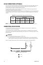
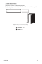
CAT5 CABLE
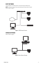
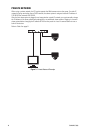
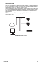
Connect a Cat5 cable to the RJ-45 network connector. The 8-pin RJ-45 connector includes video and PoE
for the dome system. PoE (IEEE 802.3af) injects power over the same cabling that carries the network data,
eliminating the need for a separate power supply; this simplifies the installation and operation of the
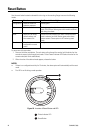
dome system without any degradation of network performance. Refer to Figure 10 for pin descriptions.
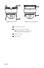
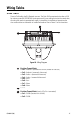
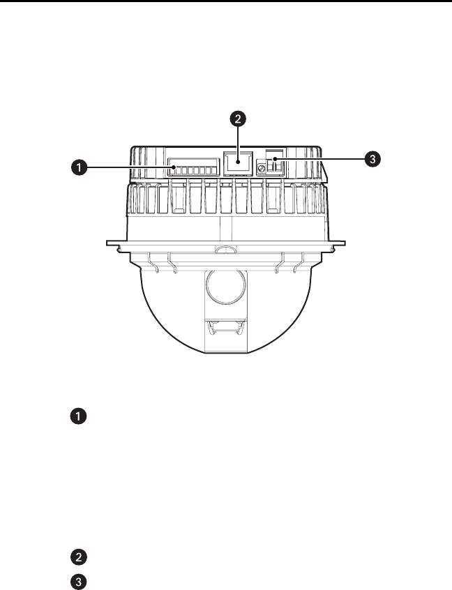
Figure 10. Wiring Diagram
8-Position Terminal Block
• Pin 1: Audio Out + (located on the far left; reserved for future use)
• Pin 2: Audio Out - (reserved for future use)
• Pin 3: Audio In + (reserved for future use)
• Pin 4: Audio In - (reserved for future use)
• Pin 5: Aux +
• Pin 6: Aux -
• Pin 7: Alarm -
• Pin 8: Alarm +
RJ-45 Connector
2-Position Terminal Block (use only if PoE is not connected)
• Pin 1: 24 VAC + (located on the far left)
• Pin 2: 24 VAC -