


12 Pelco Manual C429M-B (2/98)
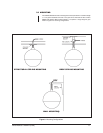
3.4 DOME INSTALLATION
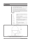
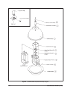
To install your dome system, perform the following steps (refer to Figure 9):
1. Select the appropriate pipe length and mounting method. If the MRCA or MRWA
mount is used, tighten the pipe to approximately 30 ft lb, then tighten the 8-32
screw in the pipe nut to lock the pipe threads. Slide the upper dome onto the
pipe and lock it out of the way with a suitable retainer.
2. Screw the mounting flange (item 4) onto the pipe and tighten securely (ap-
proximately 20 ft lb). Tighten the 8-32 screw in the pipe nut to lock the pipe
threads.
3. Align the three-hole pattern in the pan spindle with the holes in the lower
bracket (item 5), and attach with 1/4"-20 x 5/8" hex head bolts and lock wash-
ers provided. Tighten firmly.
4. Attach the upper (drive) bracket (item 3) to the bottom (spindle side) of the
pan/tilt using four (4) 8-32 x 1/2" pan head screws and lock washers provided.
Refer to Figure 9 for proper orientation.
5. Connect the installation cable to the pan/tilt and feed it through the center of
the 1-1/2" pipe. Pull the cable and connector back up into the pipe so that it
does not get caught on the rotating parts.
6. Assemble the lower bracket and pan/tilt to the mounting flange (item 4) using
1/4" x 5/8" hex head bolts and flat washers.
7. Install the camera/lens assembly onto the tilt table of the pan/tilt. Connect the
proper cables.
8. Remove the retainer from the upper dome and lower it until it seats itself on
the drive bracket.
9. Turn the system “ON” and rotate the pan/tilt. Check for cable interference. Tilt
the camera up and down and check for clearance of all moving parts.
10. After all tests have been done and the system is functioning properly, attach
the safety chain to the upper dome with the fasteners provided. Install the
lower dome and align the viewing window.
11. Check for sufficient clearance between the lens and the lower dome.
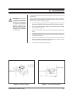
NOTE:
The small hole in the upper
dome (for safety chain attachment)
should be positioned at the back (con-
nector) end of the camera.
NOTE:
For SS20/SS22 mounting, re-
fer to steps 1, 2, 6, 7, 8, and 10. For
step 9, adjust the tilt and rotation, and
tighten all hardware.