


Pelco Manual C429M-B (2/98) 9
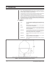
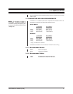
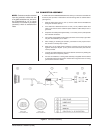
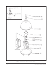
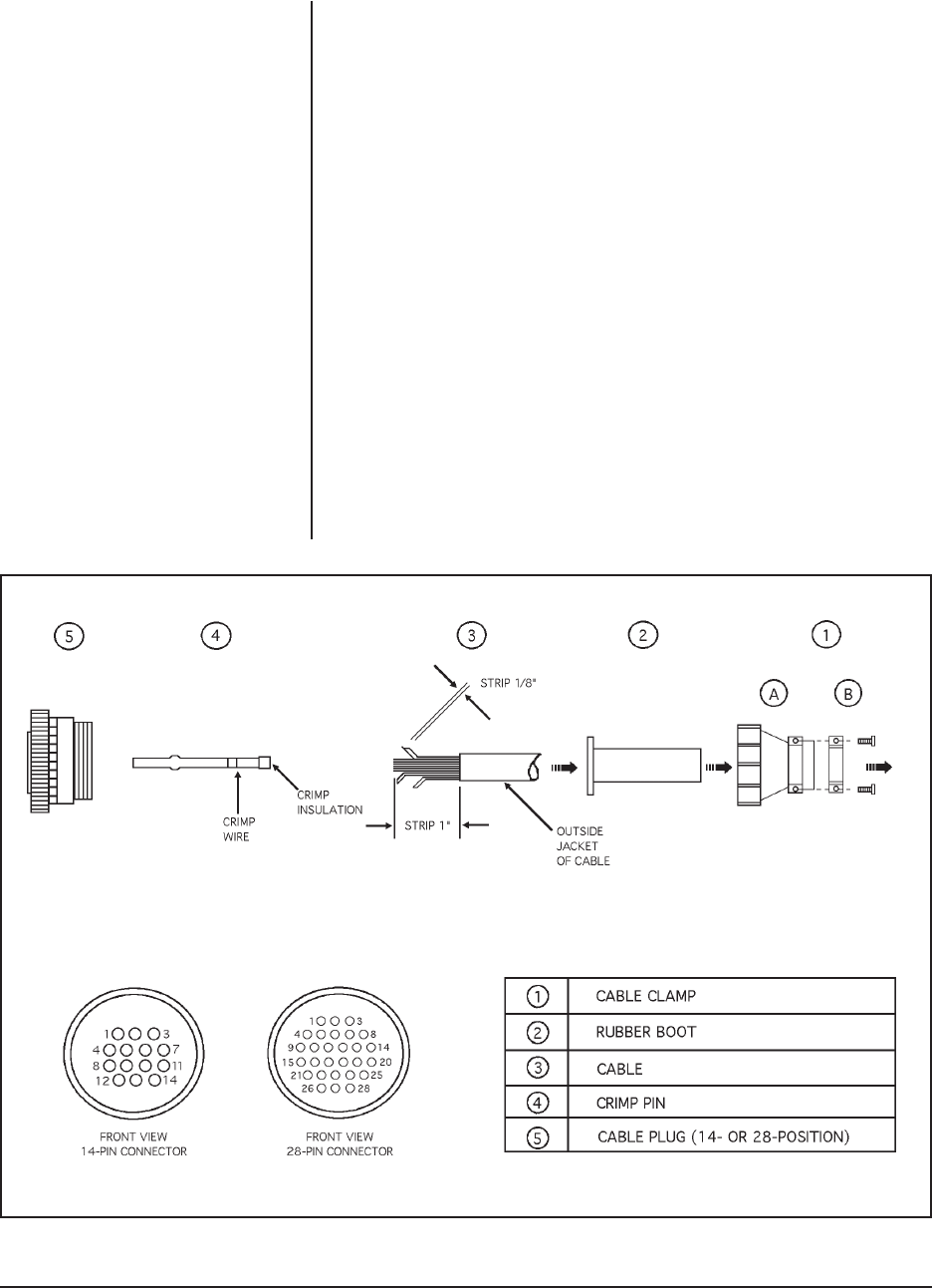
Figure 5. Connector Assembly
3.2 CONNECTOR ASSEMBLY
To install and test the SS2000/SS2002 Series dome you will need to assemble the
connector parts provided. Fabricate the interconnecting cable as outlined below
(see Figure 5):
1. Slide the cable clamp (part A , item 1) over the cable with the threaded end
facing the connector (item 5).
2. If the cable has a diameter less than 1/2 inch (1.3 cm), slide the rubber boot
(item 2) over the end of the cable and press inside the cable clamp to form a
good seal.
3. Strip back the cable jacket approximately 1-1/4 inches (3.2 cm) and separate
the individual conductors.
4. The contact pins supplied with the mating connector are the “crimp” type which
may also be soldered if you so desire.
5. After crimping or soldering the contacts, push them into the proper holes in
the connector until they snap in place.
6. Slide part A of the cable clamp toward the connector and screw the parts
together. Attach part B (item 1) onto part A and connect both parts with the
screws provided.
7. Connect the cable assembly to the unit and seat the connector by twisting the
locking collar until it snaps into position.
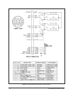
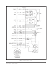
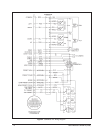
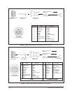
8. For ease of installation, a mating cable assembly is supplied with the domes
to extend the cable from the pan/tilt. Please refer to Figures 6 and 7 for wiring
(pin locations and color codes).
NOTE:
Contacts cannot be removed
from the connector without the use
of an AMP extraction tool, part num-
ber ZT305183 (for 9-, 14-, or 16-pin
connector) or ZT91067-2 (for 28-pin
connector), which is available from
Pelco.